The KMØT 10 and 24 GHz Beacon Project
Introduction:
In the few years that I have been involved with the microwave dish bands, the one largest question was determination of frequency. Not having a “microwave background” made it necessary for me to explore all the options, ask questions and see what the “experts” were doing.
At the beginning, operation was just to “turn it on” and see if we could find one another. This worked ok on shorter paths, but as I was reaching out for more grids, I realized that knowing the frequency of myself and the “grid hopper” was much more important. As the distances to the outer grids got greater, the actual pointing started to become a problem as well.
Now one can’t really control how well the operator is doing on the other end, one just has to be super glad that someone is actually out there “grid hopping” and trying to make it happen. So coordination calls were always filled with back and forth questions of…”are you pointed on the right heading?” and also, “are you tuning around enough?” One had to be confident in the equipment that it was actually working of course. So, the natural path was to determine which variables could be easily eliminated. The easiest one is perhaps frequency control.
Researching the methods:
So, due to the quest for more grids, I began reading about how guys were doing frequency control. The basic transverter seemed to be a bit wanting due to drift and where an actual LO would end up. The variable of temperature was a big problem.
It appeared that some folks were putting their LO crystals in the shack and keeping them at a constant temperature as best they could. Then they would run the signal up the tower to their transverters. Or they would keep the transverters in the shack and deal with feed line or waveguide losses, which is a whole other can of worms.
Then some would take it a step further and have the actual LO frequency locked to some type of standard, like a 10 MHz rubidium oscillator. This being done with some type of PLL circuitry and such was a bit more complex. The studying I was doing revealed that I was not ready to tackle those methods. My equipment was not readily set up to be modified in that manner. It probably would not have been too bad, but the locking methods of course were discovered after I had already put together my tower system and portable / rover dish systems. I made no provisions in the construction of the equipment boxes, so the retrofit was going to be time consuming and a bit more complex, so I bagged that for the time being.
OCXOs to the Rescue?
I then came across some data on a OCXO – Oven Controlled Crystal Oscillator, that appeared would do the trick. All I would have to do is figure out how to get these in my transverter enclosures and hook them directly into the crystal socket input for the transverter LO chain. That seemed easy enough so I purchased OCXOs for 5.7, 10 and 24 GHz from ID – Electronik out of Germany. These were recommended on the DB6NT website.
These arrived in good time from the EU and with a bit of messing around and learning a few things, I managed to upgrade my tower systems. I got them put back up and started operating again, only to discover that they still drifted, but not as much. The range that these held on frequency were magnitudes better than the internal transverter crystal alone, but with the temperature extremes inside a metal box on the tower still made the OCXO drift in these cases.
Modification and Testing of the DB6NT 10 GHz Transverter – OCXO Input
I then started to upgrade the rover boxes and discovered that those particular units I had built somewhat different, and there was no physical room for the OCXOs. So it looked like only half the equipment at the time was going to get the OCXO retrofit. Contest time was coming and the rebuilding on the Rover equipment would have to wait.
I also discovered another thing, when the OCXOs stabilized; they were not necessarily right where they needed to be. As a newbie, I did not realize that there was an adjustment screw to net the frequency. So there they sat up on the tower, pretty much stable, but a bit off from where they should be. If I had an accurate frequency counter at the time, I perhaps would have discovered this in time. Another lesson learned.
Weak Signal Sources:
So the research continued and I began to pick up a bit of understanding on how some folks were using weak signal sources. Some methods of doing this were fairly simple, and some a bit more complex with all sorts of PLL locking schemes, but equipment like this was not readily available in Northwest Iowa. In addition, there were no microwave beacons in the area to do a frequency check.
I figured if I could get a simple weak signal source of some type and keep it in the house, then perhaps stability would not be an issue. I also figured that I would have to measure it somehow to know the exact frequency. If I could keep the WSS on frequency, and actually hear it on the dishes up on the tower, I would know where I was. From a complexity aspect, this seemed to be the easy way out, and no further retrofitting of the tower systems would be required.
I should have bought some eBay stock…..
Again, I found what I was looking for on eBay. I came across Pyrojoe’s store and found some Macom PLO frequency bricks. I didn’t know anything about them, but the specs were such that when fed with a 50.4 or a 100.8 MHz signal, they would put out a 12096 MHz signal. A doubler added on to that from edgartech (on eBay as well) would get a signal to 24,192.000. Wow, these seemed to be the ticket!
So I picked up one of the Pyrojoe PLO bricks and some doublers from edgartech. However, other projects got in the way for a year or so and I let these things collect dust for quite some time. Thus forgetting everything I had learned in the recent past.
Trial and Error – Lesson 1:
The 24 GHz attempts made at longer paths were really frustrating me. It was a real challenge over 100 miles, and not being in control of the water vapor issue just added another problematic variable that was not helping. This again prompted me into getting a weak signal frequency source going. So I dusted off the cobwebs and started to look for ways to get a 50.4 or 100.8 MHz source. Paging through the Digikey catalogue revealed a simple TTL voltage oscillator, that were custom programmed at Digikey. They were cheap too, so I figured that was a good place to start.
So I built up a little copper pc board box and 5 volt regulator for the 100.8 MHz unit and hooked it to the Macom PLO. I also connected it to my frequency counter, but I could not seem to get any stable output, the Macom PLO was jumping all over the place from 8 to 12 GHz. I then tired to measure the 100.8 MHz oscillator source directly connected to the frequency counter. Even then I had a hard time getting a stable frequency. It appeared that the device was putting out harmonics and the counter was having a hard time distinguishing the fundamental output. If that was the case, I was sure the Macom PLO would have a hard time dealing with it too. So, I figured that I would try the 50.4 MHz oscillator, going through all the same process as tried before with the 100.8 MHz unit. I had no better luck. It appeared that the little cheap oscillators were just too dirty to have the Macom PLO lock. I even tried a bandpass filter approach to filter out the unwanted frequencies, but that resulted in little gained. These programmable oscillators were supposed have sinusoidal output, but I came to find that they were not really great frequency sources with too much square wave component.
I wanted to know if the Macom PLO was working correctly, so it was suggested to me by someone (Can’t recall who, sorry can’t give you credit :) that I should just hook my FT-817 on 50.4 MHz and attenuate the power way down. Hey, that was a great idea! Sure enough when I got the power level right, it worked fine. I tapped on the CW key to get a tone at 50.4 MHz, and the PLO locked right up and measured pretty close to 12,096 MHz on it’s output.
I wasn’t quite one step closer now, but at least I learned how to build a few little copper clad boxes!
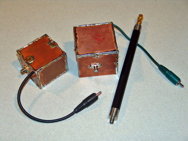
Programmable TTL Oscillators and Bandpass Filter – Copper Clad Boxes.
This did not work out too well!
More fun with PLOs:
I corresponded with Pyrojoe back and forth after I noticed on his eBay site that he was selling the same 12 GHz Macom PLO, but it now had a 108 MHz input. He also had some PLOs that had a direct 10,368.000 MHz output. I also noticed that there was another seller on eBay with 108 MHz OCXOs. Hmmmm, this got the noggin going again and I asked Joe what he thought about it. He said that he had obtained one of the 108 MHz OCXOs and it was working fine. With that I decided to get some of the new Macom 10 and 12 GHz PLO bricks and the 108 MHz OCXOs.
Tech note: The Macom PLOs were tuned by Pyrojoe in the following fashion.
For the 12 GHz PLO, the 108 MHz phase lock input is multiplied by 14 = 1512 MHz. Then that is fed to the step recovery diode circuit and harmonics are generated. The output cavity is tuned to let the 8th harmonic out. 1512 MHz X 8 = 12096 MHz. The total multiplier is 112. (108 X 112 = 12096)
For the 10 GHz PLO, the 108 MHz phase lock input is multiplied by 16 = 1728 MHz. Then that is fed to the step recovery diode circuit and harmonics are generated. The output cavity is tuned to let the 6th harmonic out. 1728 MHz X 6 = 10368 MHz. The total multiplier is 96. (108 X 96 = 10368)
These PLOs apparently work with a 96 MHz phase lock input as well, the multipliers numbers just change.
I got things in the shack and connected it all up. The measured frequency was pretty much 12,096 MHz, but there was some warm up time for the OCXO and it still was affected somewhat by ambient temperature. I ran this for a few days and started to tweak the adjustment screw on the OCXO to get it closer. This appeared to work, but even then as the ambient temperature in the shack changed, so did the OCXO. This of course affected the resulting multiplied output of the Macom PLO. This was a bit frustrating as I could never seem to get it on the same frequency over a number of days.
So I snooped around the house to find a suitable enclosure for insulating the OCXO. I found an old foam box that was used to house some trinket for the kids. In fact my oldest Patricia had done some extreme artwork on the box. But nonetheless, it was perfect for what I needed. I installed the OCXO inside the box and buttoned it all up. After a few days of running it still showed there was some drift, but it was greatly reduced. However, I could tell that if the temperature extremes around this whole mess were pretty wide, the OCXO would not do the greatest job. It appeared that the temperature that the OCXO stabilized at was just too low or needed a better heater. Oh well, it was nice to look at!
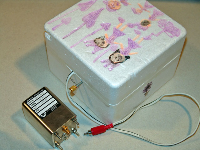
108 MHz OCXO with Insulating Box – Artwork did not help, but looked great!
The Elmers come through again!
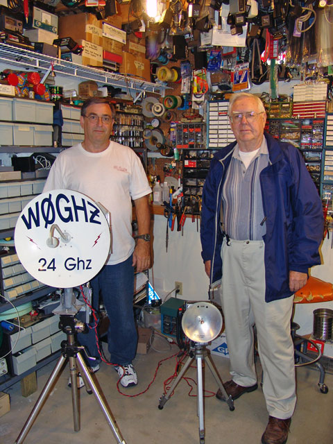
Gary – WØGHZ and Bob – WØAUS – Elmers Extraordinaire!
Gary has quite the Ham Radio Test Bench!
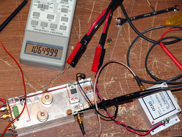
I caught up with Bob – WØAUS and Gary – WØGHZ in the EN34 area and asked if I could come over to net my frequency counter and 108 MHz OCXO. They had some nice test gear and indicated that it was “GPS Locked”, whatever that meant.
What gave me the idea to get some help was that Jon, WØZQ took one of my portable 24 GHz units over there with its new OCXO and they said that the system netted at 144.150 for the corresponding 24,192.100. So we had perhaps been chasing each other around but not looking in the right spot. If I knew Jon’s frequency, and If I had a weak signal source that was accurate to use for calibration, we could perhaps have a better go at finding one another. I just had to get my 24,192.000 source calibrated and stable.
So it all got planned and we met at Gary’s – WØGHZs QTH. He had some very nice test gear and Bob was there with his 24 GHz dish too. As we got around to hearing my PLO source and doubler after some warm up, it showed being off a few KHz from where it was supposed to be according to their gear. Since it was adjusted for my frequency counter, it showed it was right on with my gear.
Bob and Gary sat me down and explained that the gear being used was “GPS Locked” and that it was super accurate. When they were done telling me all this, I said “Soooo, that’s what that external 10 MHz BNC is for on the back of my counter!” Sure enough, they hooked the 10 MHz source into my counter and it read just like their gear. I got a great lesson in HP Z3801A GPS receivers and its 10 MHz output, along with how to use a video distribution amp to get the 10 MHz signal to multiple pieces of equipment in the shack. A good time was had but now I had to find a HP Z3801A for my frequency counter!
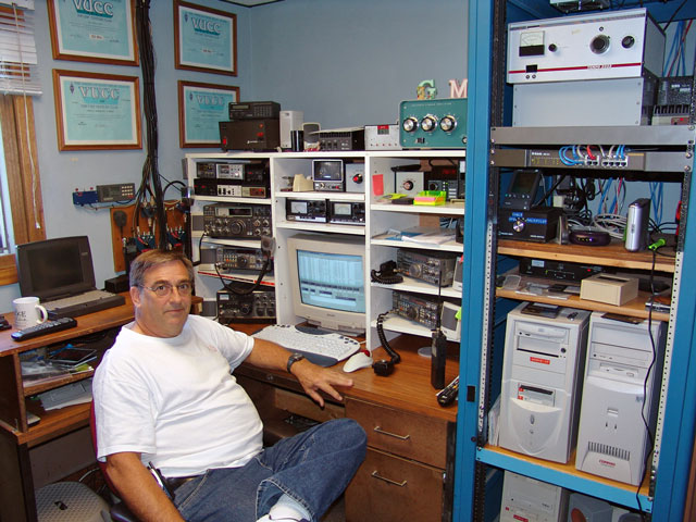
Gary in his shack giving the tour…
Trial and Error – Lesson 2:
So I was off to find a more stable source that could be used as the 108 MHz driver for the PLO. I came across the “Flash Crystal” by Expanded Spectrum Systems. This is a field reprogrammable frequency synthesizer that acts like programmable crystal oscillator. This really looked like it was a neat little circuit, and one could adjust the frequency and resolution via a PC serial port connection. Once programmed, the 10 position trimmer can select the preprogrammed frequencies and resolutions. It also had about 7 dBm of output, so it could easily be used to drive the PLO.
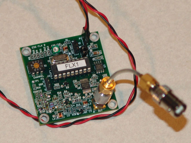
The Flash Crystal
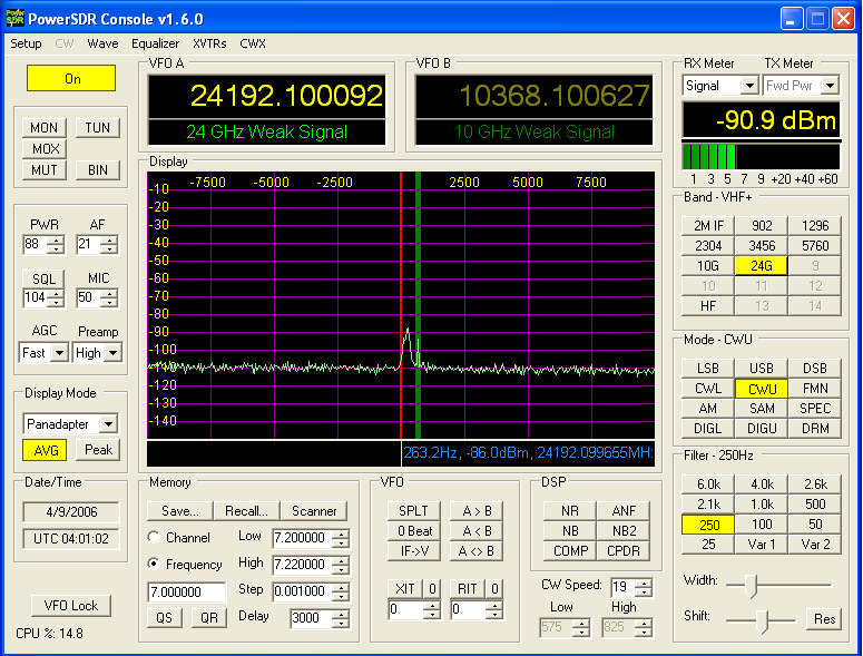
I had been using my SDR-1000 as the IF for my microwave systems, so it was evident what the 24,192.000 signal looked like when the PLO was driven with the 108 MHz OCXO. It gave a nice sharp CW tone signal on the SDR bandscope. However, when I hooked up the Flash Crystal, that is not what I saw. In fact, on one of the three “Flash Crystal” resolutions, I couldn’t get the PLO to lock. When it did lock on the other resolutions, the spectrum showed a wide hump where there should have been a nice clean CW signal. In other words, there was signal there, but it was way spread out.
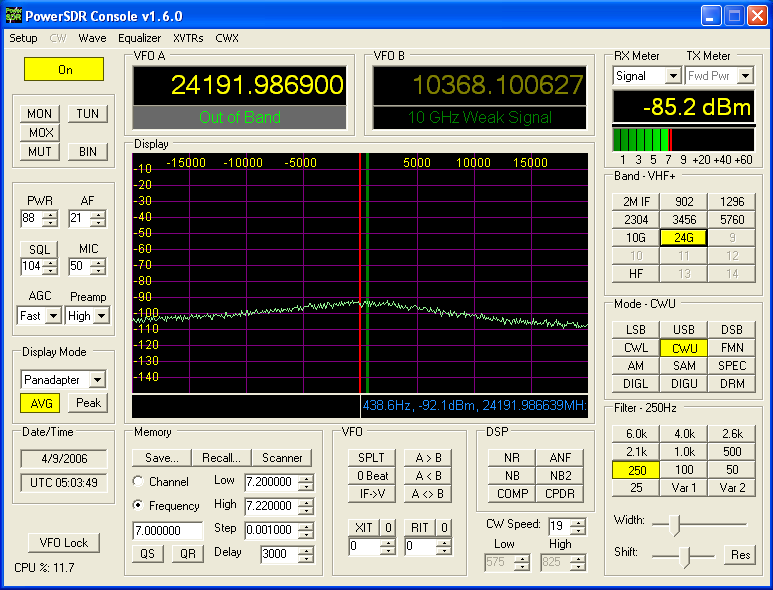
Flash Crystal at 108 MHz and the resulting multiplied output from the PLO and 2X multiplier.
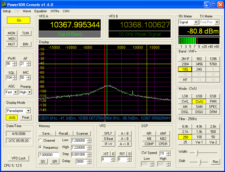
The output from the 10,368.000 Macom PLO. Note the resolution of the SDR-1000 bandscope – its + / - 20 KHz. Typically the SDR-1000 has a + / - 10 KHz width, but the new software version V1.6 allows the wider spectrum. This clearly shows the wide signal component from the Flash Crystal and the resulted multiplied output from the PLOs. Frequency was off a bit as well.
I had just got my first lesson in phase noise of oscillators. Apparently the Flash Crystal as a synthesizer was just a bit too dirty for the PLO. I was a bit stumped by this and swapped the device in and out with the 108 MHz OCXO, but sure enough it was a problem with the Flash Crystal. Al Ward – W5LUA and I had been in contact on this and he also confirmed the same exact results. It’s really a bummer that it did not work, as the Flash Crystal had an ability to input a 10 MHz source to drive it for more frequency accuracy. Perhaps someone can come up with some solution for this, as the Flash Crystal could have considerable potential as a phase lock frequency source for PLOs.
Pyrojoe give me a tip…
With that, I began thinking I was going to just have to live with the drift of the OCXO. But what I really wanted was something solid in the shack where I could really calibrate my weak signal source. Perhaps the OCXOs could be used in the field, even with their drift, just to get in the ballpark.
I recalled talking to Pyrojoe about signal sources and such and he indicated that he was using a Programmed Test Sources PTS-160 frequency synthesizer to drive his PLOs. This was an adjustable frequency source and he could configure it to what he needed in order to tune up the PLOs he was selling, as many of these required different frequencies. He indicated that lots of them were going for very reasonable prices on eBay, so I decided to take a look.
Some research began and I downloaded the specs of a Programmed Test Sources Inc. PTS-160 along with checking out all the available options. The PTS-160 is a low phase noise frequency synthesizer that can provide a variable output up to about 13 dBm and is adjustable from 0.1 to 160 MHz. There are a number of decade switches on the front panel that allow one to select the desired frequency. There were options for being able to adjust the frequency change as low as 0.1 Hz. In addition, the PTS-160 normally had an internal 10 MHz frequency reference source, but some I found on eBay did not have the internal oscillator. However, all PTS-160s had the ability to have an external 10 MHz source as the frequency reference.
One last piece of the puzzle:
In the mean time, correspondence was going back and forth with John – KØGCJ on one of his spare HP Z3801As. John already had the unit modified to accept RS-232 for computer interface monitoring and he also installed a voltage brick in the unit so it could be connected directly to 12VDC. When I received the unit from John, he included an amplified GPS antenna, so the whole device was “plug and play”. The basic HP monitoring software installed on an old laptop indicated that all was working well.
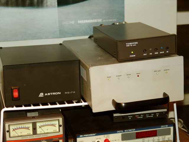
The HP Z3801A with Videotek VDA-16 Distribution Amp and dedicated Astron Power Supply
With that, I also corresponded with a fellow that had completely rebuilt a PTS-160 and he assured me it was working very well. I received the PTS-160 a few days later and began hooking that up.
With the 10 MHz output from the HP Z3801A available, I then routed that signal through a cheapo video distribution amp to my frequency counter and the PTS-160. A bit of time was spent checking the output levels from the video distribution amp to be compatible with the inputs of the frequency counter and PTS-160. A bit of added attenuation was all that was needed to connect safely to the equipment.
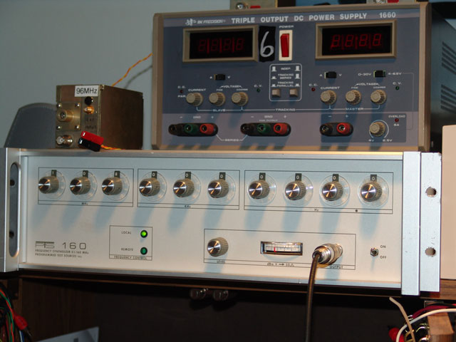
The Programmed Test Sources Inc. PTS-160
All items were powered up and I verified the 108 MHz signal from the PTS-160 with the frequency counter. That output then got connected to the Macom PLO phase lock input. The measured frequency of the PLO by itself was a stable 12096.000000 MHz. Adding the 2X multiplier to the output of the PLO then gave me a “right on the money”, 24,192.000.001 MHz.
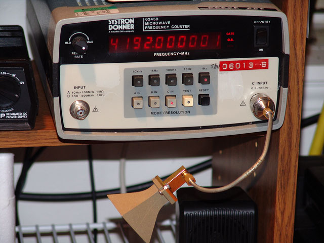
24 GHz Signal being measured… Looks pretty good!
The whole assembly produced a nice clean tone on the SDR-1000 bandscope screen, just as good as the 108 MHz OCXO! Being able to adjust the frequency of the PTS-160 in 0.1 Hz or 1 Hz steps made it easy to see the results on the SDR-1000 bandscope. One could walk the frequency up and down the band quite a ways. However, as one got farther away from the PLO integer multiplier base, it appeared that spurious signals were also be produced. With that, I felt it was safest to leave the signal source where it was set and not vary the phase lock input frequency from 108 MHz.
The only error would now be in the HP Z3801A, so I had to put my trust there. The software monitoring the HP Z3801A indicated all was still well, so I had confidence that I was within a few Hz. Not too bad at 24 GHz! I now had a weak signal source for 24 GHz running in the shack and the ability to know where I needed to tune the rig when the grid chasing begins!
The 10/24 GHz Beacon Project Is Born:
I had all I needed for an accurate 24 GHz weak signal source, but I thought it would be nice to have something for 10 GHz as well. A bit of snooping again on Pyrojoe’s eBay site again revealed that he also had some 10 GHz Macom PLOs that required a 108 MHz input to get a direct 10,368.000 MHz output. Wow, what great timing that was! I discussed getting one of those PLOs with him, but I got to thinking as well.
If I had a home base weak signal source locked on my GPS driven PTS-160, that would be just fine, but why not make a few for beacons or perhaps portable use for the rovers. I had the 108 MHz OCXOs which worked fine, but with a bit of drift. I thought that some signal source was perhaps better than nothing. If I could find out how to key the whole mess to make a CW beacon, that would be awesome too! As there were no high band beacons in the area, it sure would be nice to have one set up somewhere close, but far enough away not to overload the station.
So the conversation with Pyrojoe led to me getting 3 sets of 12,096 and 10,368 MHz PLOs, each needing a 108 MHz signal input. Joe had some of them, but had to tune a few more up to get the whole order. These arrived very quickly and I started to layout a prototype design for making a dual band beacon.
Parts and Pieces:
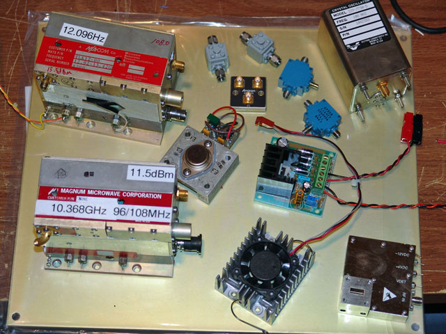
Parts for the beacon project
The first thing I needed was a way to split the phase lock 108 MHz input signal to both PLOs. A quick scan on the internet again revealed some very inexpensive passive power dividers. These looked like the ticket and the OCXO’s or PTS-160’s output was large enough to overcome the power divider loss, as the PLOs only needed 0 dBm for a solid phase lock.
I hooked these up very haphazardly just to get a feel if it would work and there were no issues. Each side of the divider output was down about 3 db.
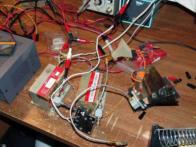
Testing the power divider to see if I could run both PLOs off of one phase lock frequency source.
While doing these tests, I realized how hot the PLOs got. So I decided to mount them on a heat sink with the power divider in between. This seemed to keep the PLOs much cooler. I even looked inside to see if there was an internal crystal heater from the previous application of the PLO, but nothing was found. I guess just the power output of these puppies make them generate a good amount of heat.
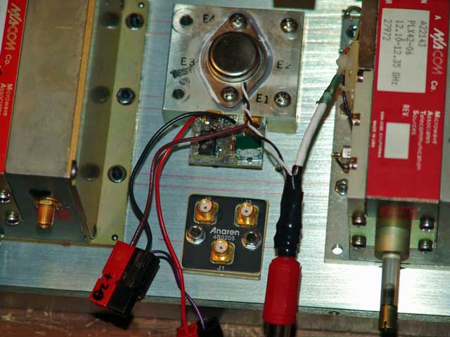
Anaren Power Divider and 20V Regulator between the PLOs.
Next was figuring how to mount the 2X multiplier to get the 24 GHz signal. The multiplier got pretty hot too, so a heat sink from an old Pentium CPU was modified and screwed on. This helped, but I still figured I would need a fan to keep it very cool.
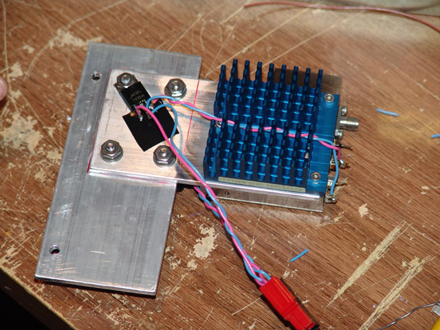
2X Multiplier with old Pentium heat sink…. 5V regulator dedicated for Multiplier power.
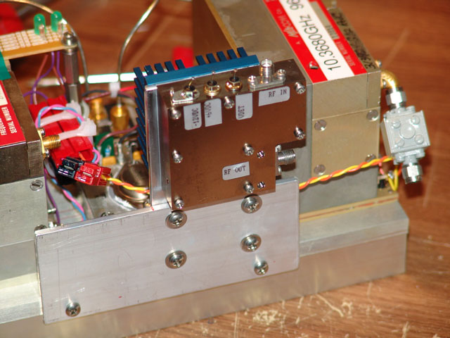
2X Multiplier mounted on the main heat sink. The -12V connection is not used.
Various circuits for powering all this were explored. I needed to start with a base voltage of 24V. A 20V regulator for the 10 GHz PLO was needed, 24V was needed for the 12 GHz PLO. Also a 6V regulator for the 2X multiplier was required; however I used a 5V regulator. A bit of experimenting indicated that the multiplier worked just fine down to about 4.5V. This all got mounted and turned on, however some of the items still got a bit warm. I mounted a 12V fan and had it blow over some of the regulator heat sinks and the 2X multiplier heat sink. This worked great and all the items operated nice and cool, but the fan noise was a bit annoying. A variable regulator circuit with a trim pot was added and I was then able to adjust the fan speed. At that point, just some testing time was needed to run the weak signal sources and adjust the fan speed for proper cooling as it related to fan noise. A happy medium was found and the whole unit was running cool without noise.
Key that mess!
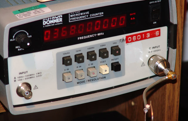
10 GHz Signal being measured… Looking even better!
At that point, I had a stable 10,368.000 and 24,192.000 weak signal source, but no modulation. So I began to ask around on how to key it. Lots of guys talked about FSK. I was told to vary the voltage to the PLOs, but that did not seem to work at all. Others talked about shifting the 108 MHz phase lock frequency, but I did not want to mess around with that. So I was back to hard keying if possible. I thought about modulating the power to the PLOs or multiplier, but was advised on a few reasons why one might not want to do that. So I kept looking around and gave a call out to Steve at DEMI.
I asked Steve what he thought about keying the 108 MHz line into the PLOs and if one of those little PCB relays might do the trick. We came to the conclusion that it probably would, but the life of the relay would be a question. It would also depend on how quick the PLO would lock and then if it would be putting out other wrong frequencies when the 108 MHz signal was not present to lock to. I then asked him about pin diode microwave solid state relays I had seen from time to time. He said those would probably be the ticket and to look into that.
Pinning down a Pin Switch:
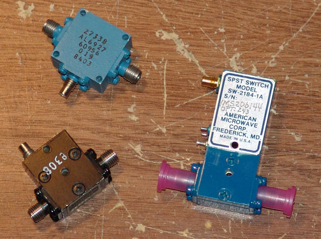
Various SPST Pin Switches
Scoping the internet and eBay gave me some names and catalog numbers of Pin Diode switches to look into. The ratings on some of these switches were in the GHz range, and since they were single pole – single throw, it seemed like all one needed to do was put one of these in line with the 10 GHz or 24 GHz signal before it got to the antenna. It would simply make or break the signal.
I called up Pyrojoe to ask what he might have. He did have a few pin switches around with various ratings, but he also indicated that one should use an isolator between the PLO output and the pin switch, as the pin switch was essentially short circuiting the PLO’s output, which is not a good thing. The pin switches he had were not “absorptive”, but “reflective” in nature, hence the needed isolator. With that, he hooked me up with a few isolators and pin switches.
In the mean time, I received a few brand new SPST pin diode switches off of eBay. These were made by American Microwave but needed some + and – voltages to make them work. These were about $20 each and looked to be quite useful. I then had to come up with some SMC plugs, as the pin switches needed this for the control voltage attachment. It also looked like I also had to build a bias power supply for the American Microwave switches.
The need for + and – voltage had not come into play here before, so this was a new concept for me. A search of the internet and asking around resulted in a simple 555 timer capacitor charge pump circuit to generate the -5V needed for the bias of the American Microwave switch. That along with a few regulators resulted in a “power supply” of sorts for the entire beacon.
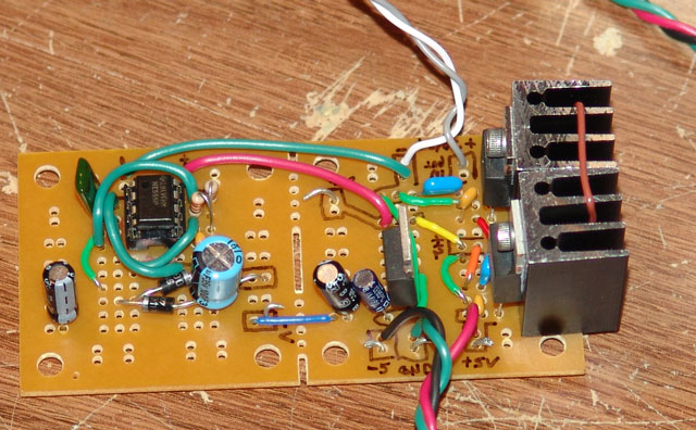
555 Charge Pump -5V supply with various regulators for the different circuit elements
Testing the American Microwave switch went well. I connected one in line with the 10 GHz output of that particular PLO. When connected in line and with no control voltage present on the SMC center pin, the pin diode switch was shorted - closed. So no signal was passed to the horn antenna. In that condition, the center pin of the control connection floated to the voltage of +5.
When I applied a ground to the SMC center pin, then the switch would open and pass the signal. Wow, that was pretty neat and the stuff was still working after I did it too! The American Microwave switch was rated for “TTL” input on the SMC control jack which gave me an idea.
I wondered if the little CW IDer XT-4 Beacon boards from Unified Microsystems I had lying around for other projects might just do the trick. I put power to the XT-4 board and programmed it with my callsign, then hooked the RCA jack output from the beacon board directly to the SMC control jack of the American Microwave switch. When I did that, I could see and hear a nice CW beacon on the SDR-1000 IF at 10 GHz. It keyed the pin diode switch just wonderfully!
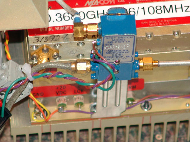
The American Microwave SPST Pin Diode switch for the 10 GHz side.
It was then time to try 24 GHz. The rating on the American Microwave switch was not that high, so I thought I might try it on the “input” to the 2X multiplier so it would only be switching the 12.096 GHz signal. This worked great and I could see the 24 GHz beacon signal on the SDR-1000 IF at 24 GHz. The XT-4 Beacon CW IDer was the perfect fit!
The SDR-1000 IF rig showing the 24 GHz beacon signal – Sharp and Clean CW!
It appeared that I had all the parts and pieces I needed and tested. Now it was time to just assemble the entire mess and do a final test.
The KMØT 10/24 GHz Beacon:
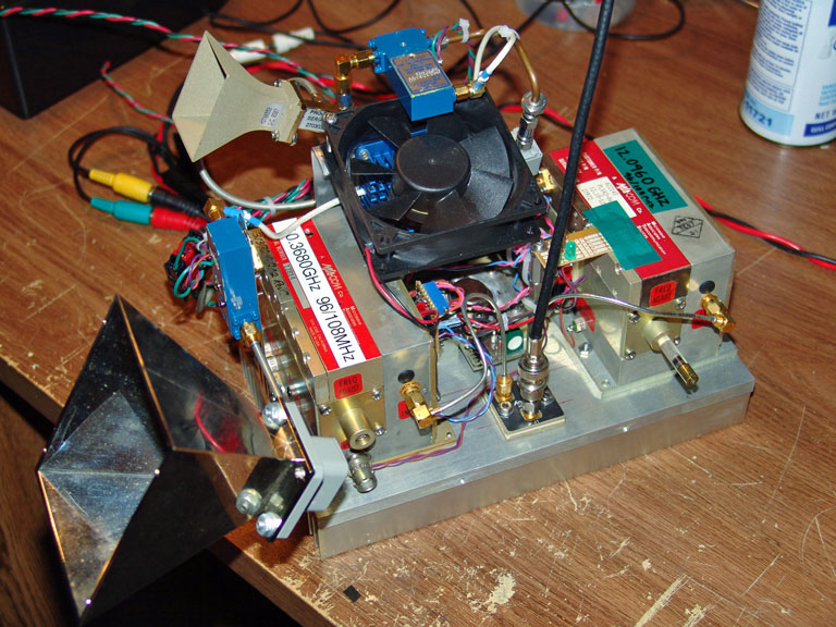
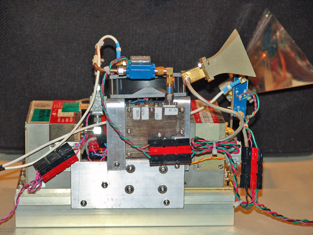
A final check of all the components was done and then the parts were all put together – here is a shot of the top prior to the fan installation.
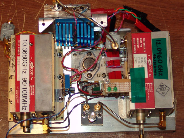
Top view prior to fan mounting
I installed the power supply components and XT-4 Beacon CW IDer inside an enclosure and used power poles for easy connection. I also had an off the shelf variable regulator to bring the 24V down to about 12V to drive the negative bias power supply for the pin diode switches.
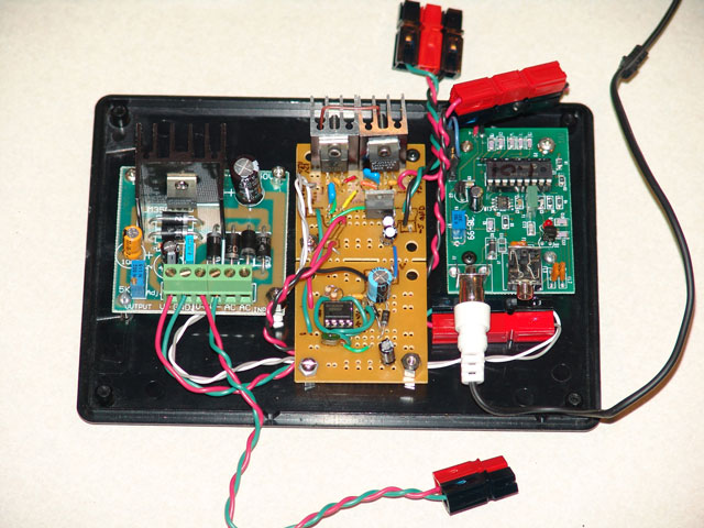
Power supply components and XT-4 CW IDer.
I also built a put together a little board to support a few LEDs. These got connected to the alarm pins on the PLOs, so that when they are not in phase lock condition, they light up. Just a nice little added touch to see if things were working.
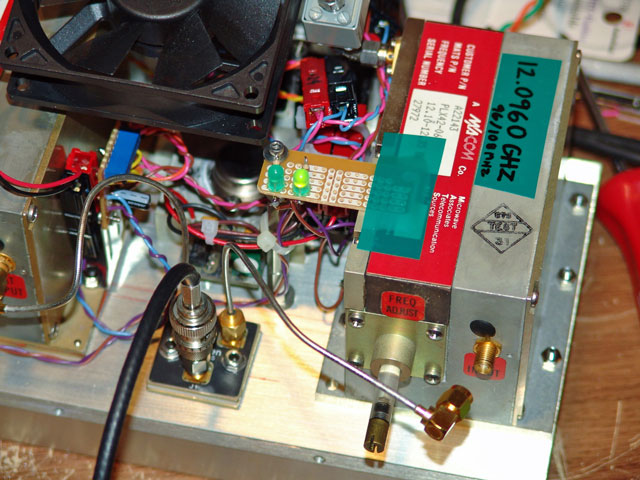
Phase lock LEDs…note the 12 GHz PLO’s 108 MHz input is disconnected.
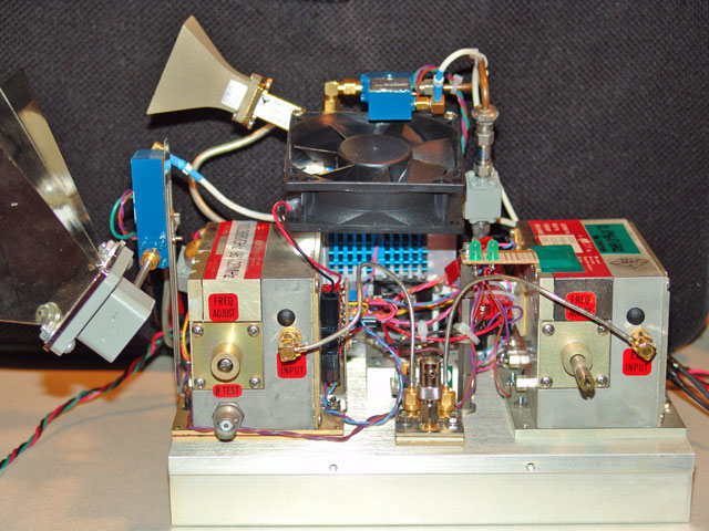
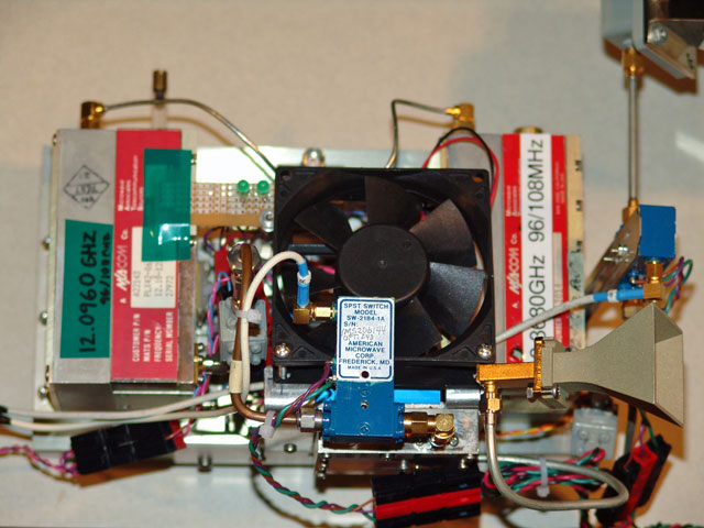
Here are a few pictures of the completed 10 / 24 GHz beacon.
Here is the block diagram. Once I got this all figured out, it seemed pretty simple. Perhaps this information will help others out so they don’t have to jump through all the same hoops I did to do this simple beacon. However, I did learn a lot and it was well worth it!
Observations:
The beacon is mounted in the basement shack, pointed out the window-well with the horn antennas angled up at 45 degrees. During the various snow and sleet storms over the 2006 winter season, I was able to watch the beacon on the SDR-1000 IF.
During the wet snow storms, I was able to view strong reflections from the beacon signal, even with its low output power. I was neat to see both parts of the signal in the SDR-1000 IF, the local pure tone and the Doppler reflected signal from the scattering medium. I guess I got my first true lesson in Doppler weather forecasting! It also did the same thing during heavy rains. I could watch the Doppler shifted signal move up and down the band. It would dance around both sides the original signal depending on the direction of the precipitation.
The wide signal is the Doppler shifted return! This was from blowing wet and large size heavy snow flakes.
Future Plans:
On the table are parts to make two more dual band 10 / 24 GHz beacons. The plan is to get these mounted in weatherproof boxes and find two suitable locations for installation. The idea would to get one about 30 miles away and the other one at 60 miles.
When implemented, I should be able to monitor these signals during various weather and humidity conditions. Taking into account dew points, wind and temperature, the idea would be to analyze the relative signal strengths and obtain some real data on 24 GHz path loss issues. Hopefully the data can be presented in a future proceedings.
Thanks for reading! 73 de KMØT