
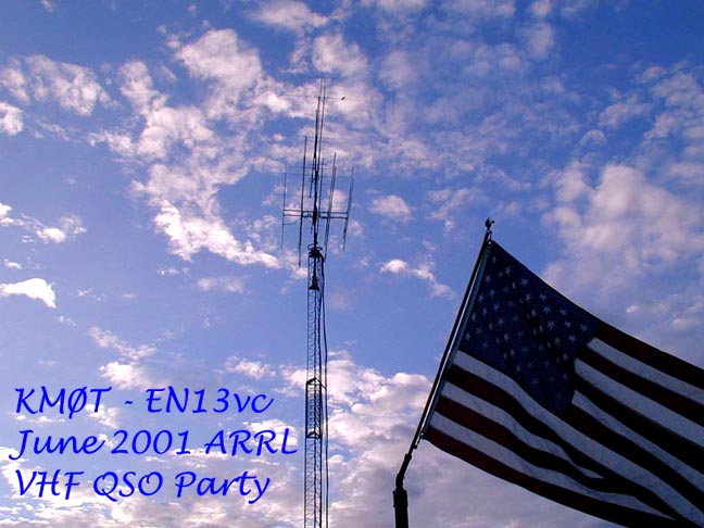
ARRL JUNE VHF CONTEST – 2001 – KMØT – EN13vc
Please read while the pictures load, there is a lot of them!"
It was not much after the steam had quit rising off the yagis and loopers from the last January contest that I began to think about the upcoming June contest. The thinking was really prompted by a few ice storms we had in the area. Rain in January was the farthest thing from my mind, but sure enough, it was raining. (Ice on the Loopers) The ice buildup was not too bad in comparison to what some other folks had in the area and down south, but nevertheless, it started the planning process.
All along I had known that I was going to somehow move my 2304 looper and mast mounted DB6NT transverter to the tower during the spring, but I just could not come up with an idea on how and where to mount the thing. The tower was full and adding another tower at this point was an idea the XYL was not too excited about. I was also toying with the idea of adding another band, like 10 Ghz, but for sure I had no space on the tower for a dish.
Sometime towards the end of January I was enjoying some reading from the "Microwave Update" that had just recently took place out east. I was intrigued by an article by David Orlean of Directive Systems Directive Systems, "Loop Yagis for 3456 Mhz." His article discussed the ins and outs of how he came about designing and testing a long boom 3456 MHz looper, all at the same time minimizing wind load rating and getting the gain near a decent sized dish. The looper designed was 112 elements and sat on a 12’ boom, the same length of his 2304 MHz 76 element design, which I could attest to worked very well. I made some good contacts with my 2304 "Blowtorch" at 30 feet and 1.25 watts during the previous contests and one during the January contest when the conditions were downright poor.
I also felt that some more activity was warranted on 902 Mhz. I had pretty good luck with my new 902 Mhz SSB Electronics transverter, with the Down East Microwave unit sitting on the shelf for future rover plans. I spoke with my friend NØDQS, Gene, about it and he seemed up for adding another band for June. With that I discussed with Steve at DEMI for getting my 902 DEMI unit upgraded and what some power options were. 902 Mhz was a great band I felt and having a rover with a bit of power on that band could help out a lot of folks, possibly prompting some new activity on the band. If the conditions were fairly good during the coming contest, there would be lots of opportunity for Gene to blow some cordless phones away!
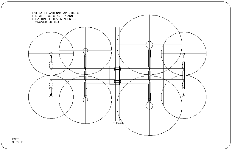
I recall discussing with Jon, WØZQ up in EN34 how he had a cross boom mast set up extended out the side for microwave antennas. I began thinking along those lines and wondered where I could put such a cross boom on the tower mast, getting the 2304 looper out of the aperture of the rest of the antennas. The wind load I felt was not a problem, the tower had capacity left, just space constraints were the issues. I was not even considering moving stuff around to make space, everything set up as it was seemed to be working fine, as good as one could get with minimal compromise of some gain and possibly aperture patterns by the multiple antennas on the mast. The layout had proven itself time and time again during the contests and various band opening. Here is a layout, showing aperture patterns of the antennas prior to the June Contest.
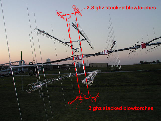
After a brief layoff of thinking about all this, the family with colds, snow flying and just trying to survive winter in general, I went back to looking at my current antenna layout. I kept going back to the cross boom idea. I took my paint program and started drawing some lines on some photos that I had of the setup, and all of a sudden it just came out on paper. If I could just have a long cross boom, mounted to the current H frame for the 1296 and 902 loopers, I could extend that frame out another 2 feet out for the 2304 MHz looper. There would be plenty of support for the cross boom due to attaching it to the current H frame. I then took a step back and thought that one antenna hanging off the side would possibly unbalance the tower in terms of wind yaw. With that I extended the cross boom out the other side. There it was, a place for the 3456 antenna, and it was essentially the same wind load since it had the same boom length. It looked like a good idea and I felt that I could mount the transveters right in the middle with short cable feeds to the loopers. I took one more look and drew a few more lines and there it was again, why not vertically stack 2304 on one side and 3456 on the other? Here is the picture I came up with during this brainstorming session.
I hurriedly sent off an email to David at Directive systems with the above picture. We discussed the ins and outs of stacking distances and how far out from the 1296 and 902 loopers the H frame should extend in order to keep out of the aperture planes of those existing antennas. The wind load I felt was more than I wanted, but with the crankup tower, I had proven to myself that when adverse conditions arose, I always faithfully cranked it down to keep it all up there. I just had to be disciplined to keep on doing that. It looked like I was adding about 3 to 4 square feet of wind loading.
I then proceeded to draw up on AutoCAD, the actual dimensions of the H frame and stacking distances. I needed precise dimensions in order to begin fabricating items during the winter. I also found a source right in town for 6061 aluminum tubing, so I did not have to worry about any of those long lengths being shipped! Here is an early AutoCAD detail of my planning.
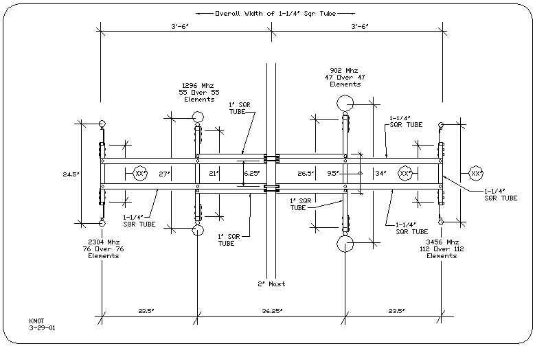
Note the "XXs" indicating distances not known at this point. David from Directive Systems and I still had to work out some details. Also, this is not how it completely turned out. It shows 1-1/4" tubing as the extension, but I ended up using 1" square. Also, the top horizontal piece of 1-1/4" as shown ended up being above the top horizontal of the existing H-Frame. Its just how it worked out with where my existing pre-amps and coax relays where located.
I need more power Scotty!
If I was going to go to all that trouble, I figured I should have a little power up on the tower. I started asking questions and looking around the web for what was available on 2304 and 3456. The guys down in Texas, (link ), Jim, KØHMC, Paul, ND2X and Ken, K5UHF at one time or another directed me to DL2AM's website. Here was a great source for higher power microwave amplifiers. I looked them over and began to wonder how one goes about getting these from overseas and also how one hooks all this stuff up. I also looked for 3456 transverter solutions. Gerry at SSB Electronics talked about how DB6NT had a new 200 mw 3456 transverter coming out that was a single box solution, no local oscillator box to add. I wasn’t even sure what that was all about anyway :) (I am learning however) I then looked at amplifier solutions for 3456 MHz. A lot of this stuff was big bucks and I needed to work within my current budget of equipment. So began the sell off of extra stuff. This made the XYL very happy.
EBay and others come through!
The hardest thing to let go was the IC-375A, the ICOM 222 MHz all mode. I got a very good price for it on eBay and had plenty to get a Down East Microwave 222 transverter for hooking up to the Yaesu FT-1000MP that I was currently running on 6M. All I needed to do was build another IF switch. (See January 2001 Contest Results and IF Switch Projects for IF switch building using SMA relays) I also had plenty left over for the upcoming purchases. I still needed more however. The Kenwood 642 FM Tribander with 144, 222 and 1296 went next. This radio had proven itself in two previous roves by NØDQS. It worked great for 222 and 1296, even on FM. But it was time to move on and make room. I had also given up on mast mounted preamps and sequencers for 144 and 432 Mhz. My feedlines were good enough and the SSB Electronics transverters worked just fine without the preamps, so they went to good homes. Lots of other stuff got liquidated as well, just did not need some of this stuff I had picked up in the previous few years. The Yaesu FT-736R however was kept for the time being, Gene would need it for the rove on 222 and possibly 1296 Mhz.
Anybody on 3456 MHz?
As far as I could tell, I would be the only one on 3456 in the area. A few guys in the Cities, EN34 and EN44 would have equipment, but it seemed a lot of work and effort just to do that. I began thinking if the budget allowed for rover set up on that band as well as 2304 MHz. I had always admired the guys who went out and braved the elements and logistics in terms of roving. It was a definite art to learn to do well and had some good technical challenges. I felt that someday that I would want to do the roving thing as well. With that in mind, I proceeded to plan for 2304 and 3456 rover "modules" I would let Gene use them for now and then when the day came I wanted to do it myself, I would be set. The equipment would be tested under fire by NØDQS. Gene seemed to think that it was a good idea, but we had lots to do in the meantime to get it all together. It was already March and June was just around the corner.
Yup, I really don’t like Heights!
After much dimensioning and drawing the AutoCAD layout for the H frame extension, I had all the info I needed except on dimension on the existing H frame. The vertical distance between the horizontal crossbooms was critical to the whole design, but I had no concrete data on what it was. My electrician friend in town, Don of TenKredit Electric, came out and gave me a ride in his bucket truck so I could get up there to measure the dimension I needed. I really did not want to lay the tower down this time of year, one could never tell what the weather was going to do.
Over the past 3 years, Don had helped me in many ways. He was involved in helping me dig my tower hole, let me borrow his truck and trailer to dispose of the dirt, sold me all kinds of stuff like Hoffman boxes to put my lighting arrestors in, switchboard copper bus bars for my grounding in the shack, kellums grips for hanging the cables off the tower, tools, special bits for drilling boxes, etc. etc. I can’t thank him enough. Everyone needs an electrician friend that is for sure.
I cranked the tower down a bit and Don sent me up there, tape measure in hand. I had never ridden in a bucket before, and as a child, could never take looking over a roof edge. I guess those things kinda stick with a guy, so this was a big deal for me. After I had settled down a bit, I took some time to look around. Even with the height I was at, about 25 feet lower than the total extension of the tower, I could see in all directions no problem. I could really tell where I had good take off for all the antennas, a very great and clear shot up to the EN34 area. Wish I would have had my camera along, but I was not thinking! On the way down, we took the 2304 Mhz looper / mast mounted transverter off the side of the house. I was going to put that unit in the prototype rover box. Gene, NØDQS happened to be over that day and I got to yell dimensions down to him. He thought it was pretty funny I was a bit green when I came down. But hey, this is Ham Radio, something about venturing into the unknown!
I Don’t Speak German!
During all of this, I had been emailing DL2AM back and forth about getting a deal on 2304 MHz amplifiers. I decided I needed two units, one for the mast mount transverter on the tower and one for the rover box. After much investigation, I had decided on the ET-40WA units. 34 watts out with 1.75 watts in. These units I was told would do about 28 watts with 1.25 to 1.5 watts input. That is where the DB6NT transverter power output is at. I also looked at the 22 watt units from DL2AM, but the slightly higher power unit was not that much more. With the emails going back in forth, It was a bit hard to get used to the written English coming from Mr. Prinz, but I think we had it all worked out. I’m sure he had a hard time with my questions as well.
We came to a price and I then wondered how to pay him. On the suggestion of another, I investigated at my local bank on how to send Deutsche Marks. What I eventually came up with was that I wrote the bank a check, and with a minor charge, they converted it into DM, with a check made out to Mr. Prinz. This would then be drawn on a bank on Frankfurt or something. This apparently was not a big deal for them in conjunction with the Wells Fargo bank, which must have an international branch or something.
I then headed off to the post office and sent the check via express mail (so I could get a signature delivery conformation ) and low and behold, the amplifiers showed up two weeks later. Very slick.
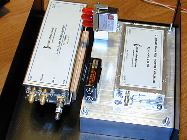
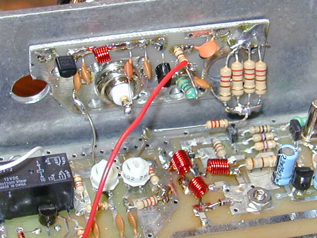
All the instructions came in German, so I went to Babblefish.com and typed in the German for an English translation. I could get the gist of it, but some technical terms and words just did not come out. Here are a few technical details on this fine looking little bricks.
This is a FET type amplifier, which has some special operating characteristics I found. The power FET will draw pretty much a great percentage of full current while just waiting for drive. So depending on how the amplifier is built, one needs to switch the 12V to the amplifier along with the PTT, or the amplifier has a separate switched 12V bias controlled along with the PTT. The DL2AM amplifiers have an inrush circuit so they can have the complete 12V switched on PTT without destroying the FET. DB6NT amps have non switched and switched 12V inputs.
2304 Rover Box – The Prototype:
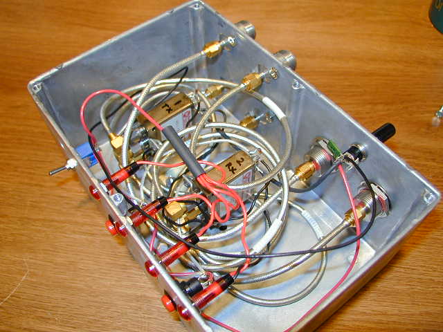
Now that the 2304 Mhz amplifiers were here, I needed to get started on the first rover box. I had the DB6NT transverter from my previous mast mount 2304 setup, a heat sink from ebay and some parts and pieces from Radio Shack and Digikey. The box I was putting all this in is the same type of box I put my SSB Electronics 902 transverter in. See the September Contest Results for the 902 MHz box.
A few other critical items came from "Pyrojoeseph" of eBay. He sold me some SMA cables and SMA to N bulkheads. These items I bought directly from him just by emailing him and asking if he had them. I don’t know where he gets this stuff, but from what I can tell I was getting a good deal. Joe has always treated me very fair!
The bulkheads were about $10 apiece, the best I could previously find was $25 for new Mil Spec devices. The cables were made in Germany and are re-shapeable solid outer conductor with solid insulation. The connectors were all soldered units with corrosion caps. Rated to 6 Ghz I am told. I got a whole bag of cables, and I am using them throughout the rest of my projects.
Since both the transverter and DL2AM amplifier have a DC monitor that tracks their respective power out, I thought it would be neat to monitor these voltages somehow. I had been looking at MCM Electronics website and catalogs. There was this 12V LCD DC monitor they were advertising as a device to monitor DC voltage for car stereo amps, etc. I searched the web for more specifics and sent emails to a few on specific questions on the device. Well everyone I heard from had a different answer. (And all turned out to be wrong) I ordered a few and decided to find out for myself what made these things tick.
Here is the scoop. They come with 3 ranges of measurement, 200MV, 20V or 200V. Depending on how the voltage divider is setup, gives you these ranges. The unit requires a separate power supply from the actual voltage being monitored. I used a 9V battery with a switch. That seemed to work well. There is a jumper for setting the decimal point.
The documentation is horrible on these things, so experimentation had to take place to get one to work. I don’t know who these people hire to write this stuff, but they are definitely getting paid too much! After messing around by moving a 100 meg resistor and digging up a 1meg resistor to make the voltage divider work, I was able to get it to measure on the 20V scale. I tested it with a few voltages and it seemed to be within a tenth of a volt of my VOM. Close enough for Amateur work! These LCD voltmeters cant be of the highest quality, one out of the 4 that I ordered came DOA, but at $11 each, they are a good value compared to other LCD voltmeters I have priced.
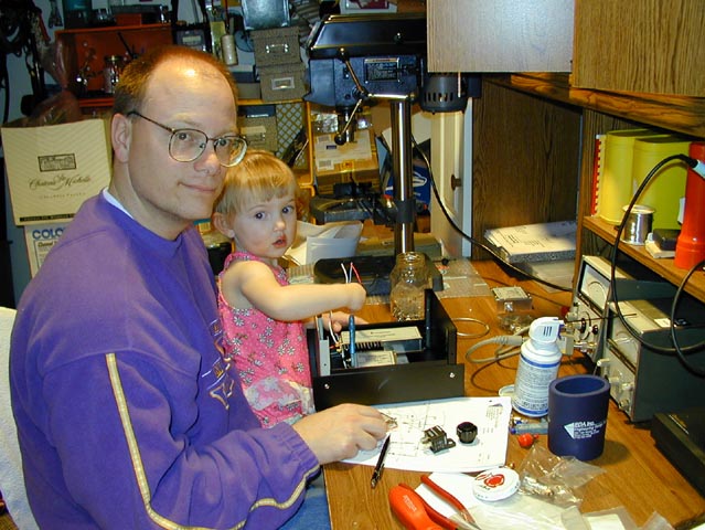
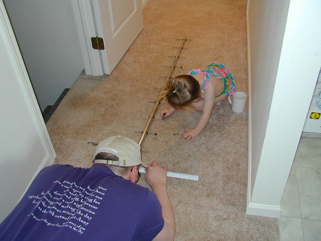
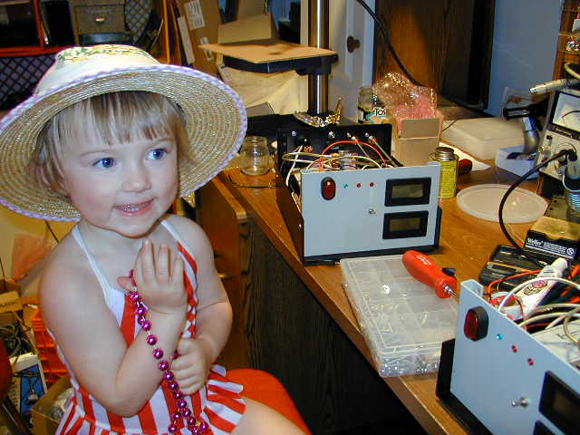
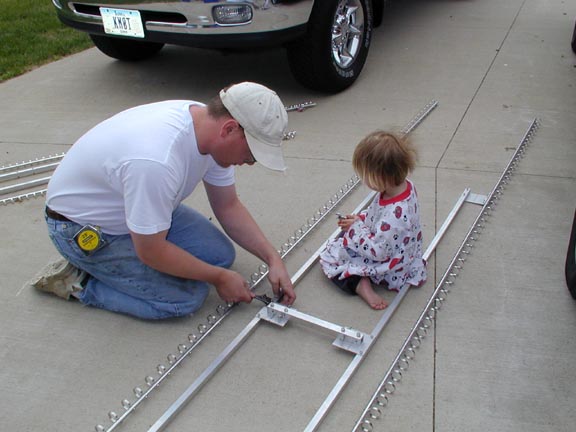
So I started drilling and cutting, wiring etc, then I was done with the 2304 rover box in Mid March. Here are some pictures of Patricia and I working on the unit.
Basic Microwave Power Measurement – On the Job Training!
Knowing I was going to be going over 2.3 GHz in the future, I began asking around on how one goes about measuring power at some of the microwave frequencies. I know I had some bird slugs that went to 2.3 Ghz, but how would I measure power at 3.4 GHz? I put some wattmeter questions out on the NLRS Reflector and got some good answers back from the guys on how to and what kind of equipment to look for or build. (Thanks Donn WA2VOI and Gary WØGHZ!) Anyway, I started looking for things like absorption power meters, power attenuators, directional couplers, dBm power sensors, all things that were new to the vocabulary.
I ended up with an HP 435B, cable and 8481A Power Sensor off of eBay. The specification on the sensor is that its rated at 100 mW max. So the idea is that you plug your rig into the power meter sensor to measure your power output, as long as your rig is no more than 100 mw output.
In most instances, this may not be the case, so that is where the attenuators come it. Notice that the meter face shows a dBm scale. dBm is a way to measure power, referenced to a certain scale. To just say you measured 3 db does not tell you anything except you have doubled your power, but from what? dBm is referenced to 1 mW – or Zero dBm. So 3 dBm would be 2 mW. There are conversion charts I found on the Internet that show watts for zero dBm to 60 dBm. If you were in the sound industry, they use the same idea, but they are called dBa. Their reference being an industry standard that is something useful for their type of work. Here is dBm chart below:
I tested the meter by putting it on the 1 mW scale and plugged the sensor into the test jack. If all goes well, the test jack is supposed to put out 1 mW, so the meter on the dBm scale would read zero, or full scale. Then, with a 3 dB attenuator put in line between the test jack and sensor, the scale would show –3 dBm. That’s the whole concept. If you need to measure high power, then you need a bunch of attenuation. Also, the accuracy of the measurement is only as good as the quality and accuracy of your attenuators.
I first tested my IF radio, a Kenwood TR-751A. I wanted to drop the power down as low as I could for driving the rover transverters. I was able to measure 3 watts on a bird wattmeter while adjusting some drive pots inside the radio. I then proceeded to figure out what attenuators I needed to measure power with the HP 435B. I had no previous experience with this meter, so I needed some practice on how to do it, also to validate that it was actually working.
I used 30 dB, 2 db and 3db attenuators all connected together to the sensor and had the HP meter on the 1 mW scale and saw a result of 0 dBm when I keyed the Kenwood 751A. I than correlated that with a dBm value of 35 by looking it up on the chart, wow it says 3 watts! So the Bird was very accurate at 144 MHz.
I then knew I had almost 40 watts of power to measure at 2304. I measured it on my 50 watt Bird slug rated for 1800 MHz. I knew that it should be close. I don't remember what it said exactly for watts, but I was in the ballpark. I then looked up on the dBm chart for 40 watts, that was a 46 dBm value. So I put 50 db of attenuation on the unit and fired it up. I got –5.5 dBm on the meter, so I removed 5 dB and continued, there I saw about -0.5 dBm. This correlated for around 44.5 dBm, or 28 to 30 watts, right about where it should be according to the specs of the transverter. (The transverter only puts out about 1.25 watts, and the amp takes 1.75 to drive it to full output, so this was right in line with the power output diagram included with the DL2AM amplifier) My 2304 Roverbox was complete, 30 watts and all!
You may ask, why go to all the trouble use this HP meter when you got the same results from the Bird meter? Well, I am not aware of any slugs that go any higher in frequency than 2.3 Ghz for Birds. Also, unless you have the correct slug and are reading near full scale, the Bird accuracy in no better than 5 percent. Microwave power meters can measure much more accurately, and at lower powers and higher frequency than your standard VHF/UHF wattmeter. (Up to 12 GHz mine is rated for by the sensor)
Long Yagis Rule!
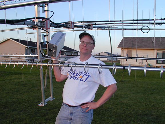
In the beginning of April, I received a M-Squared 902 MHz yagi. It has a 15’-4" boom and is very robust. I selected this antenna for Gene’s Roving Machine. I really have liked the looper performance I have had, but I felt a yagi for the rover would stand up a bit better. The 902 Loop yagi loops are fairly big and could bend a bit in the 70 to 80 MPH speeds that the rover driver will subject them too! Patricia and I spent a few nights putting it together and Gene picked it up a few days after that. It was at that time that Gene had decided to buy my FT-736R, so he was picking that up as well. This way he could have an IF driver on 2M and 222 and 1296 right out of the box. Here is a picture of Patricia showing me how to build the 902 yagi.
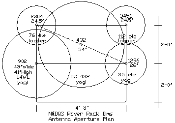
I had worked out on CADD the apertures for the rover antennas, and Gene was starting to work on the rack for the Rovermobile. It appeared that we would have no interaction with the antennas we were planning with a fairly small rack size. Here is a picture of the analysis of the antenna apertures in order to figure their spacing.
Rover IF Switch:
Setting and planning the rover, which I have actually never done before, presented some things that I needed to work through. First off, I thought trying to mimic some of the way I have been doing things in the shack was a good start, but making it more simple. It seemed a natural to go with an IF switch that was robust and only had to switch one RF line per transverter. The DB6NT transverters had combined TX / RX on the IF side, and I knew I could modify my DEMI 902 transverter to be combined as well.
First off, for the IF switch, I wanted to go with 12V, but finding a multi-pole switch at that voltage was next to impossible without paying an arm and a leg. I had lots of 28V units, but was trying to avoid them.
Leave it to luck and eBay! I saw a 6 pole 12V SMA microwave relay come up on eBay and Ken, K5UHF beat me out on it! I really thought I was screwed. Well, a few days later another one came up and I did not let it get by me. It was brand new and was still in the shrink wrap. It did not have feedback contacts, but I figured I could work something out for knowing if it switched properly.
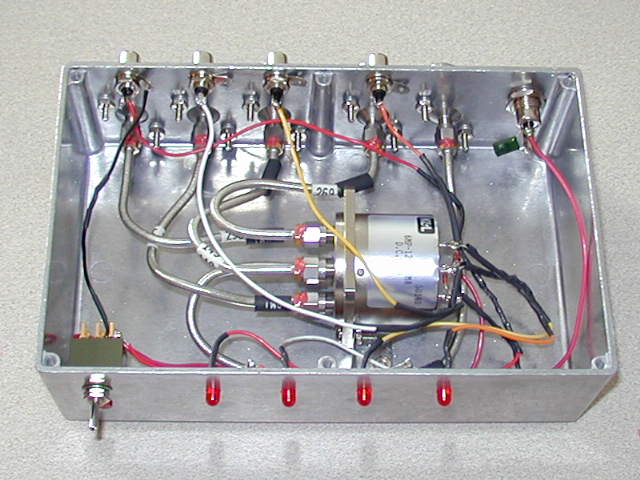
So Patricia and I proceeded to lay out the schematic and build the switch, it did turn out pretty well. I used microwave cables of various sizes that I had gathered in the last year. This thing could switch up to 10 GHZ would be my guess If I had to. At 144 MHz, it really has great isolation and not any VSWR bump that I could tell from my MFJ analyzer. I piggybacked some LED indicators on the 12V that switched the various positions. These don’t give a true indication of positive closure feedback, but better than nothing.
The SMA and N bulkheads were from "Pyrojoeseph". I know that N connectors were a little overkill for the IF lines, but as the rover, I wanted no chance of damaging smaller SMA connectors and cables.
We got done with this one around the beginning of April. Here is the result!
The Aurora Gets Me in Gear! Another IF switch done in the heat of Battle!
I had recently let my IC-375 go and then Gene bought my IC-736R. I had nothing on 222 Mhz. The plan was to get a 222 transverter from DEMI and incorporate it into the FT-1000MP that I was using on 6 Meters. This of course meant another IF switch. I was starting to get tired of building them!
I came across a small SMA relay on eBay, it was 12V and I thought "wow this would be a find!" When I got the relay, I realized that it was not a SPDT switch with a normally closed contact. It was one that needed a momentary 12V pulse on either of two contacts to make it switch from Position 1 to Position 2. It also had feedback contacts to indicate positive contact in either position.
I really was not happy about it, thinking that I would not find a use for it. Then I realized that this could be exactly what I was looking for if I was going to only have two rigs to switch! But I needed two units, one for TX and one for the RX side.
Lo and behold, another one of the same came up for auction and I got that one too, each around $30 each, not really expensive. I felt that for just switching two rigs, this would be ideal. Just having two momentary contact switches would be all I needed to switch the relays. No constant power draw to heat up the relays either. Also, the switch could be used in the last position with the power off, so there were some distinct advantages of using these types of relays, other than only being able to switch two transverters.
I started working on the switch, but the transverter had not shown up yet. Then in the first week of April, major solar flares were happening and the aurora was coming! I sure did not want to miss any fun! The night before the transverter showed up, I finished the switch. The next day when the transverter came, I began the hook up. It was then I realized that I had totally forgot how I was to implement the PTT switching between the two transverters.
Some quick thinking led to me getting a momentary contact two coil latching DPDT relay shipped down from Digikey. (The DPDT relay is not shown in the picture below, took it before I remembered to do it!) This way I could switch both the hot and ground of the IF PTT line to either of the two transverters, using the same momentary contact switches that were controlling the RF relays. During one of my lunch periods I did the drilling in the box and then I came home a bit early from work and wired it up, listening to AU signals loud and clear on 2M. All went as planned and I made it on the air to make 10 or so 222 Mhz AU QSOs on April 11th. The DEMI 222 Transverter and FT-1000MP combo was as good or better than I anticipated. Thanks Steve!
Here is a picture of the complete unit, it is my best IF switch yet! I think the latching RF relay is the way to go. Now to find them in 12V and more than 2 poles!!
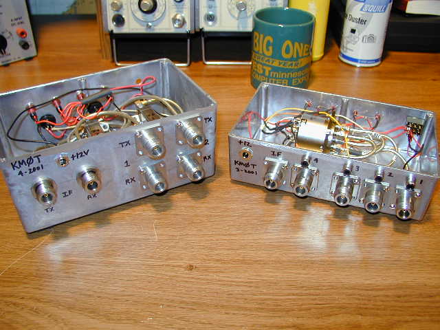
Here are both the new switches being displayed for show!
3456 Mhz – Time to get the 2nd Rover Box Done!
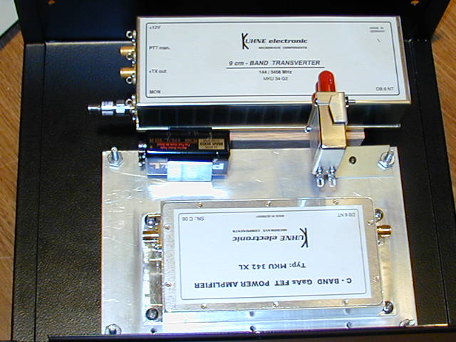
I kept checking with Gerry at SSB Electronics and he said that the 2304 transverter for the tower and the 3456 MHz transverters and amp were on their way! It was mid April.
As soon as they all got there, I proceeded to work on the 3456 rover module. It came together a bit faster and better than the 2304 prototype I built. The only technical difference other than band of operation was that the transverter put out 200+ mW right out of the box. Therefore I needed to add a 3 dB SMA attenuator to the input amplifier. The DB6NT amplifiers I ended up with produce 15 to 16 watts with 100 mW of drive. These are amazing little devices and look extremely professionally made.
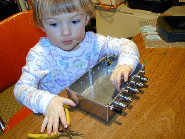
After the 3456 MHz rover module was done, I tested it out with great anticipation. I was able to get 15 watts out of the unit! Patricia was very pleased with the performance as you can see!
How did I break that?
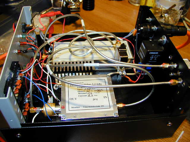
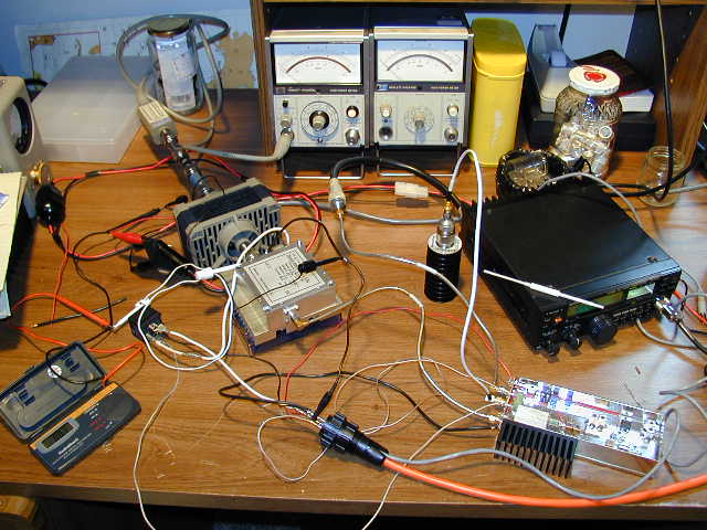
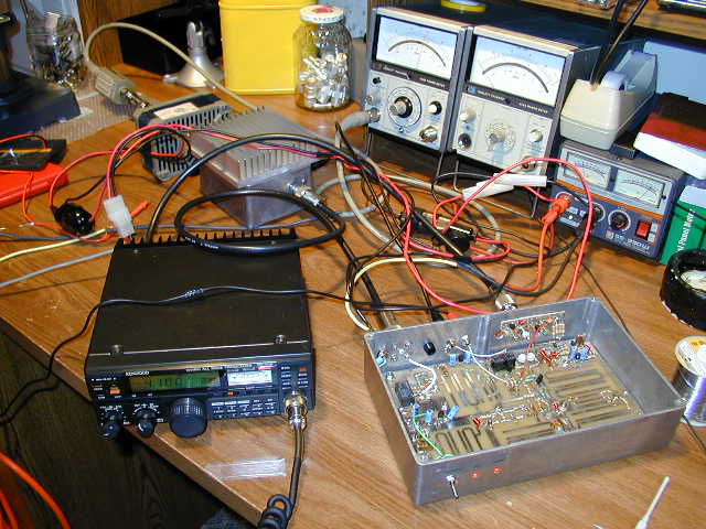
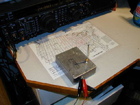
One of the little snags I ran into in along the way was right after I tested the 3456 rover module, I decided to test the 2304 rover module again just for grins. It had been built for almost a month now and not fired up for some time. Well, I couldn't get any power out! I was at my wits end. How did I break the thing? It was working just fine when I tested it out, now nothing. Because of this, I decided to take the amp out and bench test it with the other 2304 transverter that was destined for the tower project. I set up all the power and relaying for the 12V switched input to the amp, still nothing. Hmmm, next I took the identical amplifier that was destined for the tower project and connected it. Yes, I had power just like I had when I tested the 2304 rover module. Back again, swapping the amps, nothing. There was definitely something wrong with the DL2AM amp. Here is the bench test setup.
Lots of thoughts of having the language barrier describing the problem, sending it back to Germany, would it be back in time? etc, etc. I really knew nothing of how to fix these things.
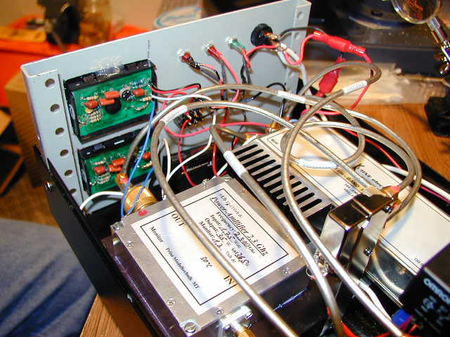
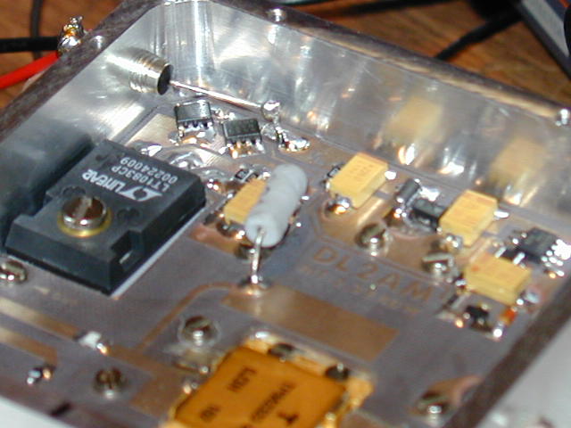
Well, I decided to call Gerry at SSB Electronics. He told me about "quiescent current" and a few more things about FET amps. I got a schematic faxed to him. After some review, he suggested I go and open the amp up and make some measurements with him. I did this, got it all hooked up and no current on key up. According to Gerry, this thing should be drawing some juice.
Well, I opened it up and was thinking of probing the 12V line to make sure that the voltage was past the feed through capacitor. Well, as I touched the lead inside the case with the VOM probe, I saw a small spark and noticed that the current jumped. Ahhh mannn, now what did I toast? Close inspection on the wire coming through the feed through capacitor and where it was soldered to the board indicated a problem. The power wire was broke right at the point of contact, stress or whatever, too sharp of a bend in the wire at the solder point, etc. had caused this lead to break. My guess is that it happened during the cooling down period after I first tested the 2304 rover module.
Some quick but delicate work with the soldering iron and a new wire extension to the circuit board got it all back together. Wow! I fixed my first microwave amp! Thanks to Gerry at SSB for giving me some confidence on getting inside that thing. It is a work of art!
I got the 2304 rover box back together and tested. With both the 2304 and 3456 rover modules done, I decided it was a good time to bench test the equipment that was going in the tower box. This worked out very well and I got some good data on the power outputs of the amps and transverters.
Dig Into 902:
In mid May, I received my 902 transverter and 50 watt amplifier from Steve at DEMI. All power levels were good, however it still needed to have a combined TX/RX on the IF side for the rover setup. Steve sent me their kit for that option and I jumped right in.
I never really built a whole lot before so winding a coil and such was kinda like…."Hmmm, is it going to work?" Not to worry, it came together and worked like a charm. Here is a picture of the add on board that does it.
Here is a picture of the DEMI 902 Transverter and 50 Watt amplifier being bench tested. The DEMI 902 amp works very well and gives a solid 50 Watts output!
"Menards" Special Rover Equipment Rack:
Now that I had the three "rover modules" done, I was going to build a rack of sorts to mount all the equipment on. I had listened to Jim’s (KØMHC) presentation at the Aurora 2001 Conference. He had talked about things in terms of mounting equipment and some examples of what he had done in the past. Showing his rover racks up to how they evolved to the present. He also set a good criteria for himself in terms of time, "1 hour" for equipment mounting and take down for his roving setup.
Over some days, I pondered what I was going to do. One day I was in Sioux City and decided to drop by Menards to look at threaded rod, metal shelving, etc., just to get ideas. While I was there I saw these plastic storage shelving units. I did some mental calculations and decided that this was what I needed. Note the A/V switchbox on top of the middle rover module with the control cables. This switchbox selects the appropriate transverter and routes the RF through the IF switchbox and also routes the PTT line from the IF rig to the corresponding transverter, works like a charm!
It turned out really well. The double legs make the top shelf very sturdy. The plastic is easily drilled and easy to mount cables and equipment too. Just some care needs to be taken to use washers where needed. This shelving unit came with 5 shelves, I only used two. My wife was pleased that she got a 3 level shelf for some of her stuff!
Tower Box – 2304 and 3456 MHz:
Most of my time had been spent doing the rover stuff and planning for the antennas for the rover and tower. Not much time had been dedicated to working on the tower box. One reason was that all the equipment was not here all winter, but the main reason was that I was not sure what kind of box I was going to use and how I was going to heat sink it. (A little procrastination took place as well and next thing I knew, it was about 3 weeks to contest time!)
I had a specific list of things I wanted in a box. Size, weight, construction, weathering ability, and cost were all considerations. I think the biggest things to me were physical size and weight. I just had a problem with adding square footage to the wind rating and weight to my tower. Along those lines, how the box was going to be physically mounted played a part, simply because I wanted to have as small as possible impact on the antenna apertures. From the early analysis, it looked that is was going to fit very well. (See the diagram earlier up the page)
This had been pondered for many hours, I had even considered making my own box but abandoned that after deciding I would have trouble weatherproofing it. With that, I looked at commercial "Hoffman" boxes and got to their website, www.hoffmanonline.com The neat thing about Hoffman online is that when you register, you can get line drawings or .PDF files for their enclosures.
I drew up all my transverters, amps, relays, etc and had the Hoffman boxes on CAD as well. I spent a few months arranging and rearranging the layouts of transverters and amps in the various boxes. Main considerations here were the ease of access to the equipment for repair and getting adequate heat sinking on the various pieces. The trick was to do this while keeping the box as small as possible and still be able to build it.
With the experience I had in building both the 2304 and 3456 systems from the rover modules, I knew that auxiliary components took some space and demanding some attention on their location. I drew up some wiring diagrams and tried to figure on locations for the power and RF relays along with proposed cable routing within the box. Those little hardline cables just don’t run anywhere, and as I found out some are a bit hard to bend exactly like you want.
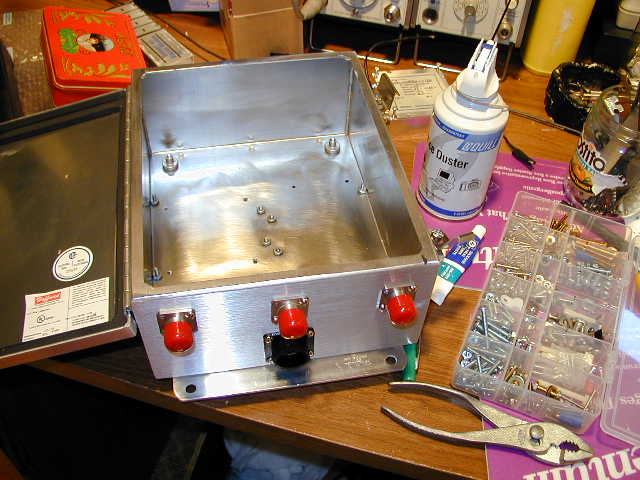
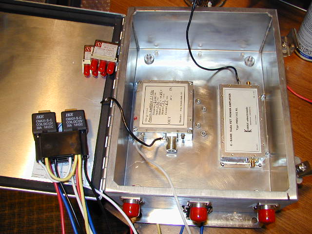
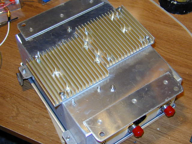
The box I decided on was a Hoffman A-1008CHAL (10X8 Aluminum with Hinged Cover) and the design layout would be a two tier approach. The amps for both bands would mount inside the box on the bottom, with heat sinking from the box itself as well as heat sink material mounted directly on the outside. The transverters would be mounted on some kind of "shelf" above their respective amplifiers. Relays and cables would mount wherever they best fit.
Here is an initial picture with the amps mounted. I have the holes drilled for the N to SMA bulkheads and the heat sinking material on the outside.
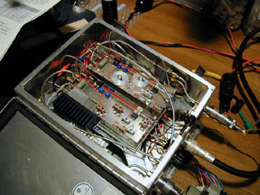
The idea was to get as much mounted to the box that would not need connecting after the transverters were mounted on their shelf and put in the box. With that in mind, a few trial cables had to be put in and bent to the approximate location. The transverter shelf would then be put in for a moment with the position of the RF hardline cables noted. Then the transverter shelf would be removed and the cables would be bent a bit more until the were on the money.
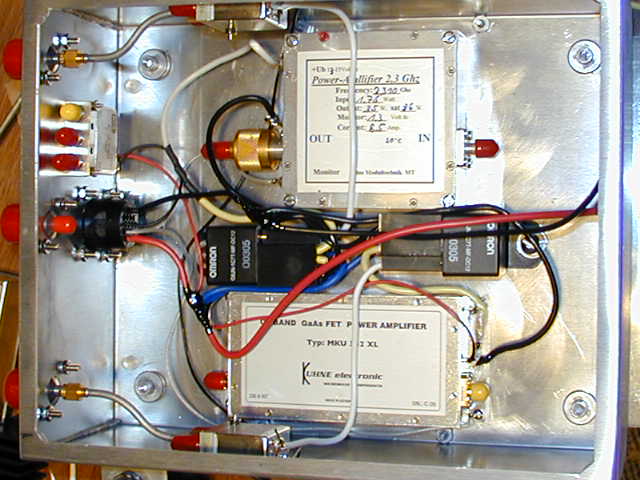
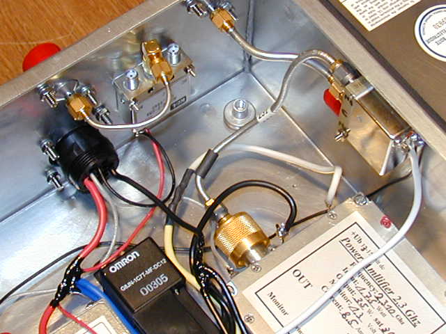
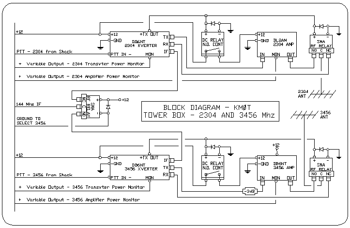
After everything was looking good, the transverters and their shelf were mounted and the cables attached. There was one additional relay on the IF side to switch the 144 MHz signal to either the 2304 or 3456 Mhz transverter. The failsafe "power off" position of this relay was on the 2304 side.
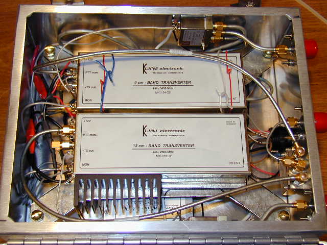
Some wiring notes: 144 MHz combined IF. Grounding the input relay switches between 2304 and 3456 MHz systems. Each system has its own PTT. Each system has two conductors down to the shack to check relative voltages on the DC voltage monitors for the amps and transverters. That way once they are tuned, one can track the power output of the system that is selected. Here are a few final pictures of the completed tower box and a block diagram of the system.
Testing the Tower Box and DC Power UP the Tower:
It was two and half weeks to contest, the tower box was done. Now I needed to test the unit. I also knew I needed to run the IF cable, control and monitor cable, and DC power up the tower. This was something else that had been taking the back burner.
I decided to run LMR-400 for the IF cable. The FT-100D in the shack was going to drive this unit, but its lowest RF level output at 144 MHz was just over 3 watts. I chose 125 feet of LMR 400 and got 2 watts at the end of the cable, an acceptable level for the transverters. Look on the Time Microwave website for their LMR Coaxial Cable "Online Attenuation Calculator."
The DC issue took a bit of thought. As an electrical engineer, I work with AC voltage drop at line voltage (120V or higher) on a regular basis. I don’t really get into it much at DC. To make things easy on myself, I downloaded the Electrical Designer's Reference Calculator, free software available to people in the electric construction industry. I ran some preliminary calculations to get a feel for what size cable I need to get up the tower.
These calculations indicated some pretty large cables to keep the Vdrop down. I then needed to decide what I felt was an acceptable drop in voltage. In order to do that, one needs to know the current of the equipment and the starting voltage.
I run my power supply in the shack at 14.3 volts. The equipment for the tower box in the 2304 MHz position peaks at around 15 amps. I decided that running the equipment at 13.8, which would be a half a volt in drop should be acceptable since this is where much of the automotive systems are running.
Considerations of size of cable up the tower needed to be done, running large DC cables was going to add considerable weight, as well as flop around in the wind.
I had done some talking with Jim, KØMHC about the voltage problem as well as a few other. Some fellows had DC supplies at the tower base, some at the top. Some had 28V to 12V converters at the top as well. This got me thinking to considered a two cable size solution. I had a total run of around 90 feet, but in reality, half of that was not a a consideration in wind and weight loading of the tower. There I would go with a cable that was large enough to have virtually no Vdrop. Then the rest of the run could be considerably smaller for weight and wind loading considerations, all keeping with the 0.5 voltage drop goal.
What I ended up with was 300 kCMIL cable from the shack power supply bus, outside across the lawn to the base of the crankup, and then up to the tower to the end of the base section. (about 21 feet is the height of the base section) This base section obviously does not crank up, so I attached the DC cables to one of the legs with sunlight resistant tie-wraps. From there, I ran #4 AWG which looped up through the coax standoff guides up to the top. See the picture of these cables. Note how the #4 AWG attaches, it runs down before it runs up. That way there is less stress in bending the smaller cable when cracking the tower up and down. I used multiple 5/8" ground rod clamps to connect the #4 to 300 kCMIL cables. This was the least expensive method and turned out to be a great solution.
Now, before I ran this DC cable and attached it to the tower, I had run the both ends into the shack and connected them in order to test the Vdrop. I did the same for the IF cable and control cables. That way when the tower work was completed, all systems should act as they were tested. The Vdrop calculations turned out to be a bit conservative. In the 2304 position, the voltage was noted at the cable end to be 13.9. On 3456, where the current draw is less, the voltage noted was approximately 14.1. This was revalidated with proper current measurements of the equipment. The 2304 systems did not draw quite 15 amps, so the lower voltage drop made sense with the EDR Vdrop Calculator.
For controls, I hooked up my AV switchbox in the shack that was currently controlling 902 and 1296, to add 2304 and 3456. It controls the PTT routing, the IF switchbox in the shack as well as the relay in the tower box to select 2304 or 3456 MHz. So no extra switching to get screwed up during the heat of the contest. Also, since I was working on this part of the system, I decided to eliminate the hand switch that controlled the shared feedline relays for 902 and 1296. Now the switchbox powered the relays when I selected the 902 position. The power off condition (Normally closed) is in the 1296 position. This worked great, no more messing around. With the one IF (The FT-100D) , I could switch 902, 1296, 2304 and 3456 by hitting one button and then transmit instantly on the band I selected.
All RF tests went well for the tower box in the shack. The HP microwave power meter confirmed 28 to 30 watts out on 2304 MHz and 15 watts on 3456 MHz. The DEMI microwave birdie generator weak signal source turned out to be invaluable to verify that the transverters were hearing where they should. Check out my little loop antennas!
Antennas and Tower Work:
I had been talking to David at Directive Systems about getting these new loopers, power dividers and phasing cables. David was getting swamped and we were both getting nervous about getting the items here prior to contest. Getting ready to go to Dayton was also a big issue for the vendors like David, you have to make hay while the sun shines. With the recent developments in the A0-40 satellite, there was plenty of Heliax antenna work for David.
A good bit of luck came to pass about a month to contest. K3MQH, Dick posted on the Internet VHF reflector to sell his 2304 loopers, power divider, phasing cables and stacking kit. They had never been out of the box. I figured it was better to get these and take that work off of David’s back. These loopers arrived in ample time and with some minor modification (phasing of the driven element on one) they were ready for half of the H frame extension.
Now David just had the 3456 MHz stuff to work on, which I felt was a big relief for him. He worked diligently on these new 3456 MHz – 112 element loopers over the Memorial Day weekend and I received them with one week to go. (Thanks for your hard work David!)
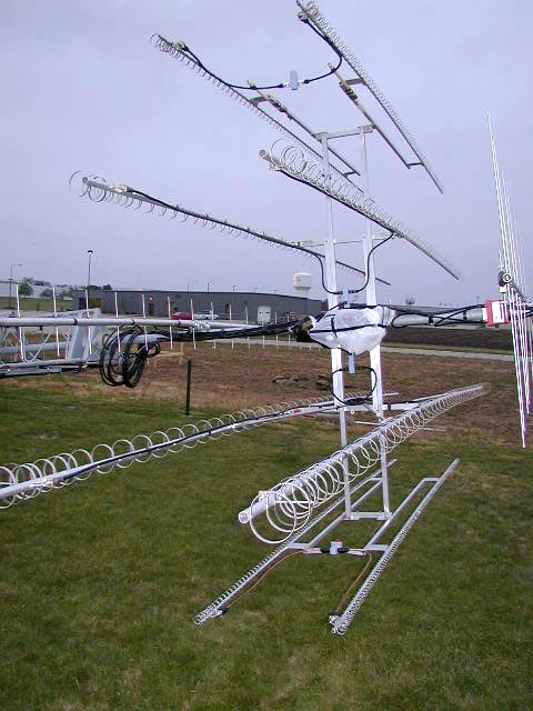
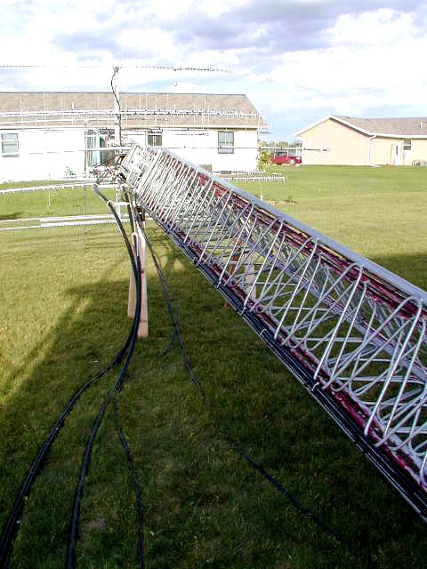
We had quite a bit of rain on and off the last week before the contest, but I managed to get the tower laid down on Saturday before the contest. When it rained, I did my metal working in the garage. I did as much as I could until the weather cleared up.
By Sunday night, I got the 2304 loopers mounted on their vertical support and got the same going for the 3456 loopers. I also had the H frame extension on the tower with all the proper holes drilled ready to accept the loopers.
NØDQS travels to EN13 for Microwave Outfitting!
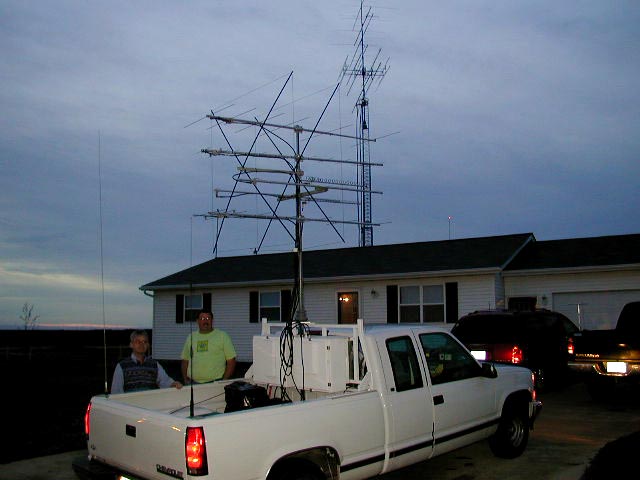
Gene, NØDQS came over late Monday afternoon with his rover mobile and the rack with antennas mounted for most of the bands.
In 25 to 30 MPH winds and scattered showers, we commenced to mount the 2304 and 3456 Mhz loopers. I also had all the ˝" superflex jumpers made by KØPW for 902, 1296, 2304 and 3456. (Congrats by the way for John's recent 2M WAS!) John had offered to make these up for me in order to save me some time. They were all about 15’ long, but cut specifically for the frequency they were going to be used at and swept for accuracy. Thanks John!! (This turned out to be the best thing I ever had done, the jumpers worked great!)
Amidst the rain, we got the rover rack with the 902, 2304 and 3456 rover modules installed and connected RF and the DC cables. Gene and I had been in close contact in the last weeks and he had the entire interior wiring ready to go, so we did not have to mess with those items that evening.
We then headed down to the shack to adjust the 144 Mhz output of the FT-736R. We had it adjusted for 2 watts output in order to feed the transverters. I had already set them up during my testing phase for 2 watts drive, so no adjustments for the transverters on the drive side had to be done.
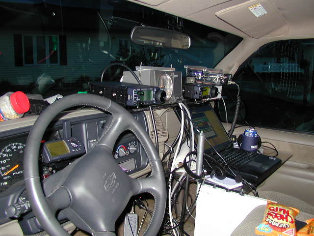
We then headed up and installed the FT-736R in the rover mobile and hooked it all up. Gene already had the PTT output ready to be connected to the IF switchbox. We routed the IF cable and was ready to test. We set the DEMI weak signal source up in the garage and took off down the road. We picked up the birdies where we were supposed to on 2304 and 3456 Mhz. I then listened for Gene on 1296 and 902 on my ICOM handheld receiver. Power output testing went well on all bands and the front panel meters on the rover modules for 2304 and 3456 were very close, no need to tune the antennas…or no time for that matter, it was Midnight! Gene took off and I hit the sack!
See the rover transverters through the front window!
Finishing up the Tower Install:
Over the next two days, I proceeded to finish mounting the 2304 and 3456 loopers on the new H-Frame extension. I then took off my 144 and 222 mast mounted preamps since the new transverters seemed to hear anything I needed to work without them being turned on. This would save some loss thought the relays in the preamps.
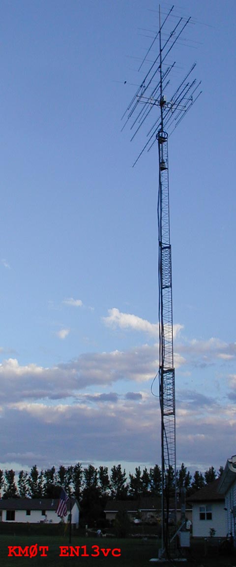
Then I looked for the best way to mount the tower box on the mast. It was almost like I planned everything from the first day I started mounting stuff on the mast. The box with ľ" square aluminum tubing extensions fit perfectly with places for the mast clamps that I could actually get to. All that was left was to get the feedlines made to feed the loopers. Looking at the picture below, it looks very much like what I drew up with my paint program for planning the installation many months before, kinda scary!
Below is a picture of the 300 kCMIL copper lines for the 12V up the tower, see how its tie wrapped to one leg of the tower that does not extend. (I know, white tie wraps break from the sun, I replaced them all after this picture with black UV resistant tie wraps.) At the top of the first tower section, the #4 AWG copper loops up with the rest of the coax cables.
I had purchased ˝" superflex jumpers that were 15’ long and had one loose N connector off of eBay. I measured off what lengths I needed and proceeded to dive in. Wednesday night was spent figuring out how to put on N connectors on ˝" superflex. It was a learning experience and took some time. I recommend doing this learning exercise while not being under the gun! Now I know why John, KØPW said putting those cables together for me was "a labor of love!" Well, I did the best I could and took as special care as I could. I knew I had no time to really test and fiddle with these cables. I had to hook them up and check the power output, no time to use a directional coupler and check for SWR levels.
Thursday evening was spent putting on the cable and weatherproofing everything, then a final test of the tower box and all the bands on the tower. All seemed to be working well, so I cranked the tower up and started cleaning up! Boy did those loopers look cool up there! At the top of the first section in the picture below, you can see how the smaller DC cables loop before running up with the coax.
TESTING – ONE TWO!
NØDQS agreed that we needed a quick test, so he ran out just north of his home town of Schleswig, IA in EN22. We started on all the normal bands, 2M, 222 and 432. We then did 1296 and was then blown away by how strong the 902 stuff was. With fingers crossed, we went to 2304. Gene was very strong there and sounded great. We then jumped to 3456 and I made my first grid on that band! Gene had his first grid on 902, 2304 and 3456! We were very pleased that all appeared to be working as expected. Months of work were coming together. Now to prepare for the contest! With a little bit of time to spare!
THE CONTEST – ARRL 2001 JUNE VHF QSO PARTY:
The map from the Hepburn Tropo Ducting Forecast did not look to bad for the weekend, however the wind had picked up a bit right before the contest but things remained fairly warm outside. Right before the contest, I was listening out east and worked a few stations via 6M Es. The contest began by grabbing a few grids out east on 6M and some in close grids to CO and NM. This lasted till around 2000 UTC. In between, I chased NØDQS/R and only found him in EN21, he must have gotten a late start. Gene was having issues with his 6M antenna, so we missed some points there but he had just gotten going. The rest of the bands were working.
Also, right at the beginning of the contest, I ran into Greg, WQØP in EM19. I managed to pick up a new state on 902! A nice surprise. The band was not in too bad of shape to the south. I had a few guys on 2M from the EN34 area tell me the 6M band was open, that’s why the high bands were kind of sparse. I listened and called a lot to check, it just was not solid 6M here in EN13.
I ran into Tim (KØPG) and Pat, K9ILT as they ran their Limited Multi-OP in EN02. We had time to chat on their 4 bands and it was good to hear Pat on the other end running things. Congratulations on your new call Pat!! They were sounding good on all bands.
At 2014 UTC I ran into K5UHF/R for a few QSOs from EN25 on 2M and 432, but then lost them. From what I could tell, things were not going well at the beginning of their monster rove back to Texas.
At 2030, NØDQS/R and I completed on all bands (except 6M) while he was in EN30. This was the farthest away he was going to be for the entire contest, we worked on SSB with no trouble on 3456 MHz. That stuff was working great! That gave us confidence for the rest of the weekend.
Then the AU hit, what a pleasant surprise. Solar activity had been low for weeks and this was pretty much unexpected. I had checked Spaceweather.com early in the morning, but It did not look like a strong enough solar wind was going to hit, so I never gave it much thought. Well at 2038, Bill, KØAWU was coming in via the aurora 59A++ on 2 Meters. With that, the grid frenzy began. I worked many on 2M and went to 6M to get some there too. I called and called on 222 MHz, but few takers, just a few grids there.
The farthest AU on 2M was K4TO in EM77 around 2241 UTC. The farthest on 222 was W9ICE in EN60. The last AU qsos were had around 2315 UTC.
I kept looking for Ken and Rick, K5UHF/R but no luck yet. I asked around and no one had heard where they were lately. In the mean time, Gene and I continued to have complete success on 2M through 3456 MHz as he traversed the grids. Signals on 902, 2304 and 34546 MHz were very amazing. Typically better than the lower bands in terms of copy, noise and QSB. They were very enjoyable to this point.
A nice surprise to hear Perry, KØKD on EN31, we got to work on the bands through 1296. Worked Gary, WØGHZ on all the bands except 3456. Never did connect there and not sure why.
Managed a few more contacts with K5UHF/R around 2130 UTC during the aurora while they were in EN26. I did not get them again until 0300 or so late that night. We managed to work on a few higher bands while they were back in EN25 and EN15 and EN24, 3456 Mhz was not working and the thunderstorm lightning static was making contacts nearly impossible with them on 6 and 2M.
While K5UHF/R was back in EN25, Jim – KØMHC/0 EN26 was calling them. They were working on all the bands and I tailed ended every time, apparently the beam heading was good enough all the way through 3456 MHz because Jim came back every time!
I had been watching the weather radar for some hours now because a large line of T-storms was headed from the Nebraska/South Dakota area and it was heading this way. I had continued to call and call for K5UHF/R, but the lightning static was so bad when pointed their way, I figured they were in the heart of the storm. However, the 6M band was open to the east coast with a vengeance. I started working QSOs to there around 0500 while watching the radar and the wind gauge.
I had to QRT at 0617, ran outside and cranked the tower down and disconnected the cables. About 3 minutes later, the winds picked up to 50+ Mph gusts, rain, lightning etc. I considered going to take a nap, but I fought the sleep and went outside to see my new H-Frame and looper addition get its first wind test!
Bummer of it all was that I was missing a HSCW schedule with Russ, K2TXB. We most likely would never had any trouble making it, just a factor of timing with the storm and all. I was able to get things going again at 0730 UTC, the storm was a fast mover. Since it was going from NW to SE, the beam heading to the NE and East was ok for more 6M. The band was still open and I proceeded to knock off some more grids.
I had a HSCW schedule with Joe, K1JT at the W3CCX station at 0800, we completed around 0830, just in time. I also had a schedule with W7KK in Nevada on HSCW. We completed during last June’s contest, but he apparently was not hearing me for I got all his information in the first half of the schedule. Next Year!!
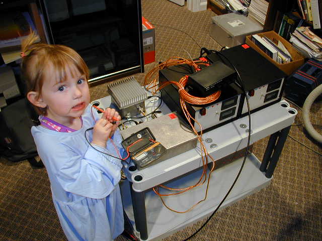
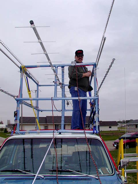
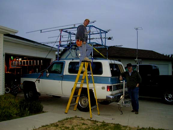
The 6M band was still open to the east but now even better to the EM and ELs to the SE. I worked 6M until about 1014 UTC and then decided to listen on 2M for a bit for k5UHF/R. I fell asleep for 10 minutes I think and then was woke up to the sound of "This is K5UHF/R in EN13!" I nearly jumped out of my chair! Good thing I had the receiver on their frequency or I might have missed them. As it turned out, they were in Sioux Center of all places, just a mile or so south of my QTH. I coaxed them to come and have an eyeball. If I had known, I would have had the coffee on!
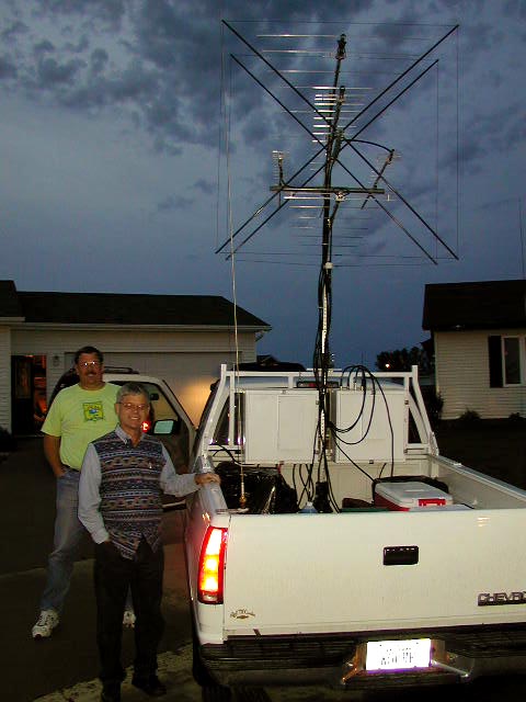
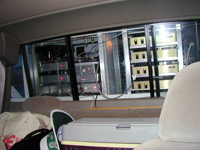
Anyway, I got to meet Ken - K5UHF and Rick - KD5ABM. I got to take a quick look and snapped the above pictures of the impressive rover setup and I got to give a quick tour of the shack. Some quick chatting and handshakes took place and they were on their way. They had quite a ways to go and they were behind! Needless to say we worked on all the bands for a few grids except 3456 Mhz. Also, as they got a bit more out, no more 222. They were not hearing well on that band.
I kept pounding 6M on and off and checking the higher bands, but QSOs there on 2M were few and far between. I had a set of schedules with W1XE out West, but no go on those. Managed to make it with Bob, K2YAZ on 222 for a schedule, but nothing higher.
I managed to make my final higher band QSOs with K5UHF/R around 1400 UTC, after that just a few QSOs as they got past EM29.
At 1420, while calling "CQ Contest" on 6M, ZF2MU in the Cayman Islands EK99 came back! Wow and new grid and new Country on 6M! Good signals for the multi-hop Es as well. Never did hear anything else down there, was hoping to hear Cuba, but never did. Tuning across the 6M band turned up Gene, NØDQS/R at about 1500 hours. He slept in a bit more than he thought he should and was working on his 6M antenna abit. He was just getting going and had lots of miles to cover.
At 1700 hours, the tropo to the west was pretty good. W1XE multi-op in DN80 was 5x5 to 5x8 on 2M SSB. We set it up and worked on 222 and 432. I then got hold of them and set it up for 902 Mhz, holy smoke, there they came out of the noise! My second new state on 902 for the weekend! It was a big highlight of the contest. Thanks George and Phil!
Shortly there after, I started tracking W7XU/R, Arliss in the grids near Wyoming. I heard his Limited Multi-Op, Holly – N0QJM tracking him, but I was having a hard time hearing him. I was only able to work him on 2M in DN83. I checked back again in about 30 minutes and worked him in DN73 Wyoming on 144, 222 and 432! Good upswing in the band enabled us to do it, because a few minutes afterwards, I was not able to copy him talking to N0QJM. Thanks Arliss for Wyoming on 222 and 432!!! Another big highlight of the contest.
The rest of the afternoon was spend chasing locals in between checking for grids on 6M. KAØPQW, Mr. 6M DXCC Larry - NØLL, WØEKZ, K2DRH, AAØF, WØOHU, WØDMR, KFØQ, K9AKS, NØPB, NØSPP and others were found. Unfortunately, it seemed that I missed quiet a few stations that I normally work. Charlie, NØAKC was a big one. I have no idea how we could have missed, I spent lots of time calling CQ to the east and NE on 2M. The band to the east was not very good at all. NO ACTIVITY OUT OF CHICAGO TO SPEAK OF! I would think they would have tons of VHFers, but the band must be crummy to them all the time. Sure missed Paul, WØUC as he was not on the bands this weekend.
When no one would answer any more on 2M and 6M, I would check on Gene, NØDQS/R. We finished up with a few minutes to spare in the contest as he made it to his last grid #16!!! Both he and I were very beat, but he had 3 hours yet to get home, now that’s dedication. My hats off to him for all the grids he activated and worked me from!
Contest Summary: KMØT SOHP
|
Band |
QSOs |
Pts |
QSO Pts |
Grids |
|
50 MHZ |
217 |
1 |
217 |
114 |
|
144 MHZ |
105 |
1 |
105 |
57 |
|
222 MHZ |
43 |
2 |
86 |
33 |
|
432 MHZ |
54 |
2 |
108 |
34 |
|
902 MHZ |
32 |
3 |
96 |
25 |
|
1296 MHZ |
31 |
3 |
93 |
24 |
|
2304 MHZ |
25 |
4 |
100 |
21 |
|
3456 MHZ |
17 |
4 |
68 |
17 |
|
Totals All Bands |
524 |
873 |
325 |
KM0T CLAIMED SCORE: 283,725
This was my best effort yet. I felt that many were missed on the higher bands however. 6M was good, but I don’t think as good as it was for others. I was very pleased.
"The Rover’s Corner" ©
What can I say, the rovers helped out. Here is the chart of Rover activity I worked:
|
BAND |
NØDQS/R |
K5UHF/R |
W7XU/R |
KBØZKX/R |
W9RLA/R |
|
50 MHZ |
9 |
4 |
0 |
0 |
1 |
|
144 MHZ |
16 |
10 |
4 |
3 |
0 |
|
222 MHZ |
16 |
3 |
2 |
0 |
0 |
|
432 MHZ |
16 |
10 |
2 |
0 |
0 |
|
902 MHZ |
16 |
7 |
0 |
0 |
0 |
|
1296 MHZ |
16 |
7 |
0 |
0 |
0 |
|
2304 MHZ |
16 |
5 |
0 |
0 |
0 |
|
3456 MHZ |
16 |
0 |
0 |
0 |
0 |
|
Total Qsos |
121 |
46 |
8 |
3 |
1 |
Total Rover QSOs = 179
Rover QSOs % of Total QSOs = 34% WOW! Who says rovers are not necessary? This is down actually in percentage from last September, but double the QSO count from last January!
As far as the new bands that Gene, NØDQS/R added for the contest, they definitely worked well. We had a good time on the 902, 2304 and 3456 Mhz bands. We were always amazed at how strong the signals were. We will have to test them again soon, but farther out to see what this stuff can really do! As you can see, he activated 16 grids! Only missed on 6M due to his antenna problems the first day.
Should have had more contacts with Ken, K5UHF/R, but with the problems and the big storm, I still think we did fairly well. Lots of missed QSOs, it could have come close to the NØDQS/R count! Nevertheless, the QSOs from Ken and Rick were very much appreciated and I look forward to when they are in this area again!
Probably could have gotten some more from Arliss, W7XU/R, but hey…how much can a guy track at one time!?? The few that I worked with him were great QSOs in terms of picking up a few new states! Thanks to Arliss and the NØQJM Multi-Op crew for keeping me in the loop!
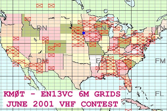
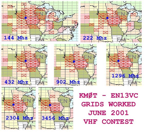
Grid Summary Chart:
Here are some grid charts showing the extent worked on the various bands. These where clipped from Vqlog, a program I am currently experimenting with. I was able to export in ADF format for my contest data from VHFDX (which I feel is superior in speed and ease of use for logging these VHF contests) The data transferred very quickly to Vqlog without any problems. The neat thing about Vqlog is that it has the ability to generate graphs, maps and charts based on the QSO data.
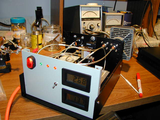
Well that's it, here's the latest shack picture. Note the portable AC unit, it keeps the shack nice and cool during the contests, it really worked well! I want to thank my Wife Colleen, who put up with all the craziness the last 6 months while I prepared for all this...I truly believe she is relieved that its over...See you on the bands.
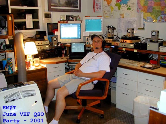
73 – Mike – KMØT EN13vc