The KMØT SDR-1000 Webpage

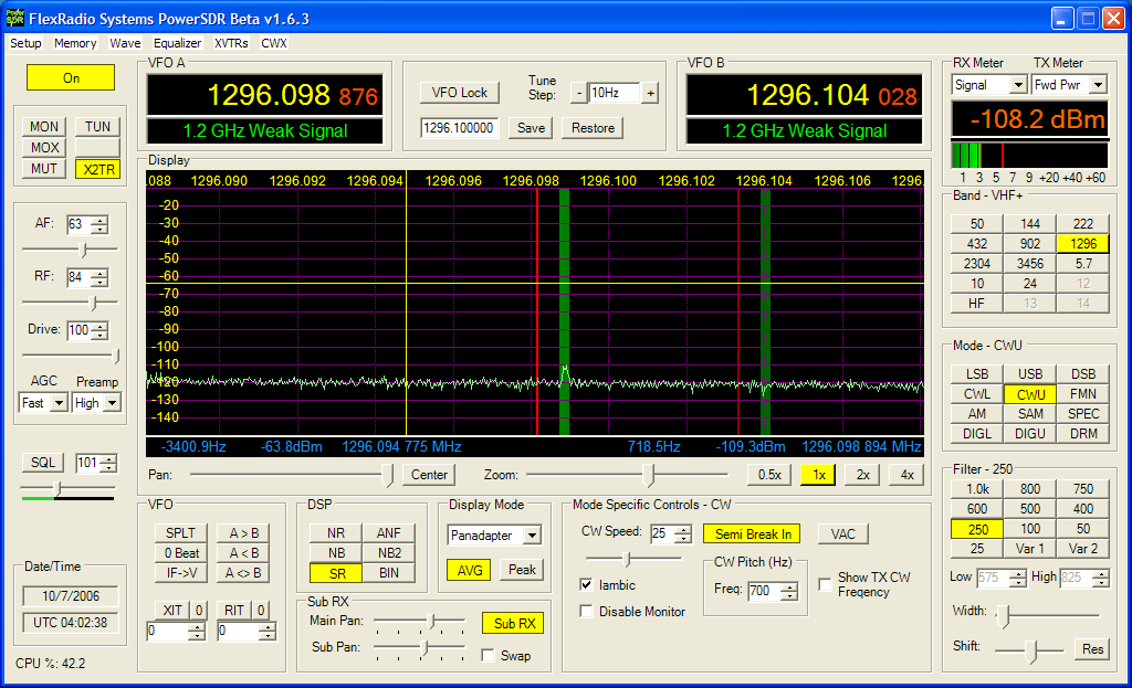
Wow! This new version of the software 1.6.3 is a monumental change from an old version 1.2 shown below - That's why SDR ROCKS! Transverter support, Dual RX and wider bandscope bandwidth support are just a few big changes! (Note version 1.8 is out and is even better!)
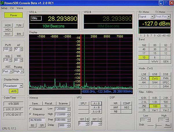
Note that this page will always be a work in progress...as is the SDR-1000!
Go to the bottom of the page for the latest update and current SDR Status.
The rest of this is how I essentially got to where I am today with the SDR-1000s.
Introduction:
Emphasis on the high bands (902 thru 10 GHz) had been a priority here at ARS KMØT for the last few years. The low bands were in pretty good shape, so not much other than standard maintenance was needed there. However, improvements to the microwave station for the high bands have been a main focus with lots of options considered along the way.
Initial operations using a FT-100D as my 144 MHz IF for the high bands worked just fine, however it became apparent unless everyone (including myself) was on a phase locked frequency reference, then finding signals were always a bit of a struggle. In order to maximize microwave QSOs during the various contests, a visual representation of the band would be ideal in helping eliminating one of the variables of making a microwave QSO. The Icom 756 series of radios with the "bandscope" seemed to be the ideal candidate for driving the microwave equipment.
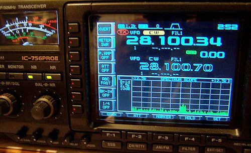
Signal from Al - WØPUF - DN84 on 10 GHz Rainscatter - Note the low resolution...
In 2002, I started using an Icom 756 Pro II as my IF radio at 28 MHz. I used that to drive a SSB Electronics LT2S 144 MHz transverter. That in turn was used to drive the microwave transverters. It was immediately evident that the bandscope was useful, but not all that sensitive. Fairly good signals on the microwave bands needed to be present in order to make good use of the bandscope.
However, this setup came to be very handy and fairly enjoyable for microwave use. Aside from the bandscope sensitivity and other operating quirks of the 756 Pro II, it was the best I could do at that point. See the Original write-up on the Icom 756 Pro II interfacing for details on this setup.
Central States VHF Society Convention - Dallas 2001
I met Ken - K5UHF from his roving expedition up here during the June VHF 2001 Contest. Ken and I had a good time working each other as he roved from North Dakota on his way back to Texas. Later on, we met up at the CSVHFS Convention in Dallas that July.
At the convention, Ken invited me to have dinner with him one night. That's where I got the opportunity to meet Gerald, AC5OG. Discussion over dinner was of Gerald's software defined radio project. Now, I was an electrical engineer by schooling, and grew up in a digital world, but boy I was blown away by the talk of the radio's architecture and technical details. However, the main question I had at the time for Gerald was "can you do a bandscope?" As I indicated I wanted to use the radio for an IF on the VHF bands and be able to see the signals. Gerald indicated at the time that it should not be a problem, "its just software!"
Over the next few years, I looked over Gerald's "SDR" and waited for it to get to a state where I thought I was ready to try it out and use it as an IF radio. Well, here we are in the year 2005 and the SDR-1000 is ready to go!
Initial SDR-1000 Implementation - late 2004
In October or so of 2004, I got my SDR-1000 from Flex Radio. I also got a new computer to run the SDR. I wanted something that was not going to take up a bunch of room in the shack, so I looked into a Shuttle XPS system. Its a nice computer for sure, small, compact and fairly quiet.
However, I had issues from the beginning with this computer. I could not get the visual basic version of the software to properly control the SDR. Numerous attempts and the trying of different parallel cables did not make any difference. With that, calls to Flex-Radio were not unanswered, but they were unable to give me a definite fix. It was suggested however to try the new Power-SDR Beta software written in C. My guess it was the computer parallel port not having enough signal to control the radio.
The new Power SDR software written in C seemed to work, but I was having other issues of intermittent audio, echo sounding signals, etc. This was tracked down to the actual interface cables I was using to connect to the computer sound card. This I pulled my hair out for a month or so until I saw a post on the Flex-Radio site about the cables to use. I had gone out and got some "gold plated" audio patch cables to hook the radio up. The information I found indicated that gold plated connector cables were not recommended because they had a slight different size than standard old silver colored connector cables. Because of this, the cables would not seat correctly and do the job they needed too. A switch to standard silver colored connector cables cleared all this up and I was off and running! I also changed computers during this process. Gave the Shuttle XPS to the wife for doing her business work and then stole the kid's Dell 8300. This was not a popular move on my part as I had to rebuild a slower PC for them which did not run their software as quick...oh well. (They eventually got it back...)
I made a few contacts on HF with the SDR-1000 which was kind of fun running QRP. I even managed to work some DX with my new SteppIR vertical antenna. I figured I was getting maybe a half a watt to the antenna. Stateside contacts on 20 meters were not a problem. Folks were amazed at the power level I was running and also very interested in the SDR-1000 radio itself. Audio reports were very good and no complaints were ever heard. Received signals were very good as well. It was neat that one could actually calibrate the frequency against known references such as WWV or local AM broadcast stations to get the SDR right on the money. In fact the SDR-1000 has a mod that can be made to actually input an external oscillator. (more on that later) Also, one can calibrate the S-Meter in order to get real world readings. This is easily accomplish by using an Elecraft XG1 signal source. Pretty inexpensive ($39) and works very slick - fun to build!
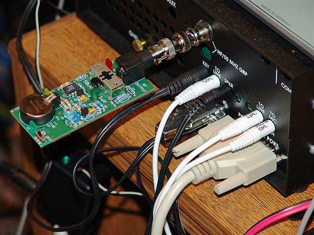
Elecraft XG1 weak signal source - used to calibrate the S-Meter...
However, a month or so later, I was starting to get some intermittent drop-outs of the receive audio. Jiggling the cables that connected the radio to the sound card did not seem to help. It was hard to reproduce the intermittent and very unpredictable. A bit of research again on the flex-radio forum site reveled that an ECO (Engineering Change Order) had been made by flex-radio. This was an approved "mod" that required one to solder a short jumper between the "digital ground" and an "analog ground" planes on one of the boards. Apparently there was a voltage differential between these planes and they needed to be at the same potential.
One other mod I did which was not "factory approved" but accomplished by Tony - KB9YIG, was to solder 4 jumper wires between two of the SDR circuit boards. The idea was to jumper across the same connections being made by a "pin-header" between the boards. The pins in question were paths for some kind of the digital / analog ground signals. Apparently, some of the ground potentials between the boards were different if the "pin-header" connector did not mate properly. (The below picture was originally posted on Ken's awesome SDR-1000 website - N9VV.com and is now reposted here.)
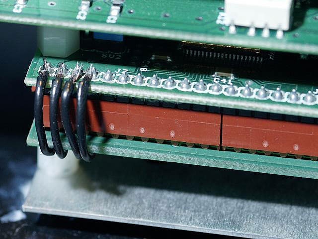
KB9YIG - Grounding Mod
After the mods were made, all was well and I have not repeated the receive drop-out problem since. Now I want to say that not everyone had this problem, and I have no idea why I did. But it was an issue I had to deal with. The flex-radio forum information was invaluable for finding and resolving the problem.
SDR-1000 and 144 MHz Transverter Integration - early 2005
I had come to a point where I was comfortable with the SDR-1000 software and its stability, so it was time to interface the radio to drive a 144 MHz transverter. I decided to use the same transverter I had been using before as my 144 MHz source, a SSB Electronics LT2S. This transverter is capable of 20 watts out, but again I could adjust it for the 3 watts out which was what I needed to drive the microwave transverters.
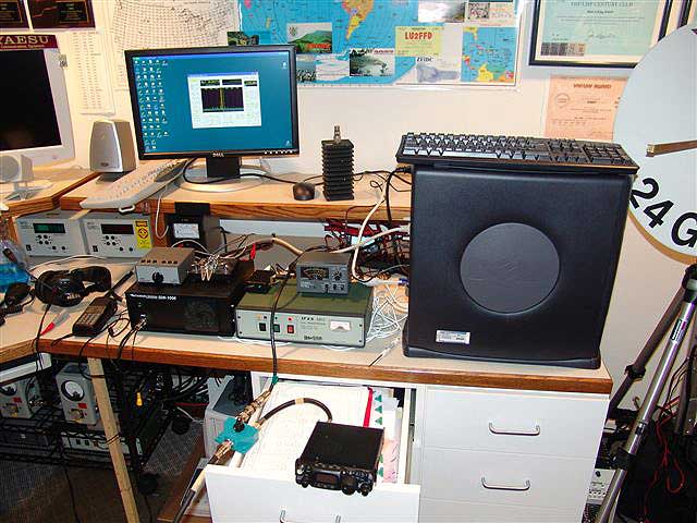
Early SDR-1000 Integration with the LT2S transverter....testing and benchmarking against the FT-817 as a 144 MHz IF.
I began to do the integration and found that when I hooked up the PTT INPUT line to the SDR-1000 front mic connector, it would only PTT the voice modes. A bit of asking around indicated that there was a separate PTT INPUT line for CW. This PTT INPUT line was only available on the back DB15 connector on the radio. Strange I thought, separate PTT lines, but apparently this had to do with totally separate software modules used to generate voice modes, verses CW mode. However, some calls and emails to flex-radio resulted in them programming an available pin on the DB15 connector as a common PTT INPUT line...aint software great?!!! This was a very big deal for me and also I'm sure it resolved the same issue for other SDR users that wanted common PTT.
From that, I also interfaced from the back DB15 connector the "sequenced" PTT OUTPUT from the SDR-1000. That is what I connected to the 144 MHz and other higher band transverters. This sequenced PTT OUTPUT had a user defined software delay built into it. It allows the SDR to wait a bit to actually transmit after being put in PTT TX mode. This is very nice for us VHF/Microwave guys as it allows all the relays to switch prior to any RF coming out of the SDR-1000!
From previous experience, I decided not to allow any direct connection to the "sequenced" PTT OUTPUT, so I built a little interface box. The output was connected to a small pcb relay. This relay via its contacts then connected directly to ground all PTTs needed upstream. With this, the SDR-1000 was isolated and all worked well to PTT the upstream transverters.
Within the interface box, I also used another relay to control the TX/RX relay for the LT2S transverter. I wanted to keep the SDR-1000 as "un-modded" as I could and use the common BNC RF jack on the radio to drive the LT2S. Since the LT2S has separate TX / RX lines for the IF drive and receive at 28 MHz, I needed to use another relay to switch the common RF line out of the SDR-1000. This was the same relay used with my IC-756 Pro II with LT2S transverter setup, as the configuration was exactly the same.
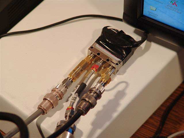
Dow-Key SMA Relay - 12V - interfaced to switch the 28 MHz RF of the SDR to the split IF of the LT2S...
I had also obtained an Elecraft 144 MHz transverter kit, which I planned on building in common IF configuration. When that was done, then the Dow-Key relay as shown could get eliminated. However, during my early benchmarking and testing, I was not able to get around to building the Elecraft transverter. So I stuck with the LT2S for the initial testing.
More Configuration Issues....
As the testing came along, I made a number of 144 MHz SSB and CW contacts in somewhat QRP mode as the LT2S was only good for 20 watts. Doing some basic operation with the radio left me with a good feeling for how robust the SDR-1000 was, albeit some operational issues. Much of these small peculiar issues were handled by programming changes as the versions of the software were released. This was very cool to be involved with in terms of being able to give feedback and actually see some results to actual user input. Flex-Radio was very responsive to their customer base and still continues to bend over backwards to accommodate.
One thing however was TX to RX switching delay. I was using a Sound Blaster Audigy 2 ZS sound card. This card was one of the flex-radio supported sound cards, but it became apparent that as the software code improved, the TX to RX switching delay was a hardware issue with this particular card.
Some folks even came out with a small daughter board kit to be attached to the SDR-1000, which did some modifications to hold some voltages down on certain components that the AGC would not attack and slow down the transition delay. (I think that's how it works anyway....) Well, I even built this board and was about to install it, but ended up not making the final modification. Its what the Flex-Radio forum referred to as the QSD Daughterboard, which the original mod came from VK6APH.
Timing is everything in the parallel paths of hardware and software design. The software guy at Flex-Radio - Eric (and others...i,e, Bob - N4HY) had improved the code and to their credit, most if not all of the TX / RX transition delay was eliminated in software. However, some of us running the Audigy 2 ZS card still had the problem. Discussion on the forum indicated that since the software delay was eliminated, that exposed the real reason behind the delay when using the Audigy 2 ZS card. The input capacitors on the card were larger in value than some of the other supported cards, so when going from TX to RX, the caps had a longer charging time constant associated with them, hence the slow rise to receive audio. So no daughter board mod or any other software changes were going to make it any better.
I even tested this myself, as it was suggested if this was a real problem, to use a cheapo Turtle Beach Santa Cruz card. Well, I tried that card and the TX to RX transition was immediate! So, I proved it to myself and and reinstalled the Audigy 2 SZ card and lived with the delay. Why go back you ask? Well it received real good. As it's bits available for the DSP were more than the Turtle Beach card. At least I got some good surface mount soldering experience with the daughterboard kit. If anyone wants it, let me know - its ready to go! Below are a few pictures of the kit and board.
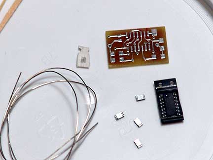
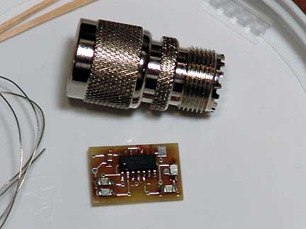
TX / RX transition - QSD Daughterboard ....one needs good eyes and a steady hand! - ( FOR SALE !)
Early January 2005 - SDR-1000 TRX circuit boards manufactured after that with serial numbers starting with "05" now have slightly different capacitor values (where I don't know...around the op amps IC7 and IC8 I think) but that apparently makes the TX/ RX transition even better!
New CPU - eBay saves me from the kids!
The kids were complaining about their computer, which forced me to start the quest for a new CPU for the SDR-1000. My talk about using a Commodor 64 when I was a kid didn't go too far....
So with that eBay had some good Dell's for sale at 100s less than Dell itself. I ended up getting a new Dell 8400 3.2 GHz with a gig of ram. I installed my Audigy 2 ZS card in it and got things all hooked up. This computer has more horsepower than what is required for the SDR-1000, but at $400 it was a bargin.
However I liked to run the SDR-1000 in the bandscope mode with the averaging turned on. I experimented with the averaging time setting and also increased the "Frame per Second" up to 30 FPS. This increases the CPU load about 20%, but still well within the parameters of what the CPU could handle.
A few other things I tried in hope for better operation was the USB connection adapter in lieu of the parallel port connection and the parallel port booster. I first tried the parallel port booster, but for some reason it did not work on my computer at all. In fact the radio did not work when it was connected up via this booster. I double checked the voltage connections I had to solder to power the booster, but all was well. I never did get this to work, but I really was not experiencing any control issues. I only had a 3' parallel cable and needed a longer one to install the SDR-1000 on the desk where I wanted, so with a longer cable, I figured I might need the booster.
So, I went with the USB adapter. This installed and worked just fine, however I found that the USB circuit produced a number of large birdies down around 144.100 MHz. This was not good, so I threw that back in the box. With that experiment over, I purchased a high quality 6' parallel cable from Flex-Radio. The cable worked fine and that's what I am using now with no issues.
After that, the kids got their computer back...
External Frequency Source
I noticed while operating the SDR-1000, my frequency would drift a bit. One neat thing is that within the calibration settings of the software, one can configure a frequency correction factor. This is great for getting everything right on the money! But this did not help my drifting issue. My guess is that the temperature variance within the shack was the culprit. So I began to look into a "locked" frequency reference since the SDR-1000 would also support an external source.
I found Rubidium 10 MHz sources on eBay and settled on one from Mitek. This is standard 10 MHz source put into a nice case and has an external LED for indicating lock after it warms up. It also came with the DC 28V power supply and fans within the case. After power up, the source goes into "lock" after about 4 minutes.
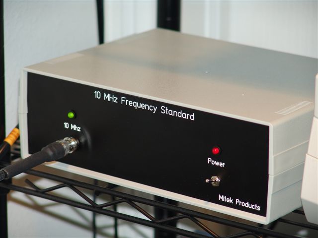 Mitek Products 10 MHz Rubidium Source....
The external frequency source adapter kit is available from Flex-Radio for about $10. What it contains is a socket for installing in the same socket where the crystal is, a small RF cable, a precision 50 Ohm resistor and BNC panel jack. I looked over the schematic and the instructions from the kit. With that I had a few questions and called Gerald at Flex-Radio to clarify a few things.
The SDR-1000 requires between 4 and 14 dBM for the external source. My Mitek source was measured at 8 dBM so it seemed to be just right. After removing the crystal and making the RF cable hook up, all one had to do was move a few jumpers. Talk about great foresight on Gerald's part to have this mod so easy to make!
Here are a few pictures of the modification.
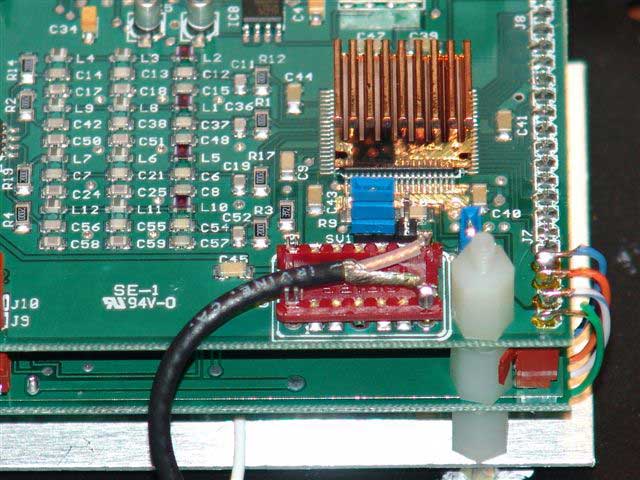
200 MHz Crystal Replacement socket with RF cable attached....note my grounding mod with the colored wires on the right.....
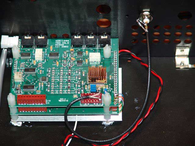
BNC Connector panel mounted for interconnection of the external 10 MHz source.
After the modification, all one has to do is go into the SDR-1000 console setup menu and enable the use of an external source and set the correct multiplier. The internal crystal is 200 MHz, so my 10 MHz source required the multiplier of 20. One neat thing again is you can still do a correction offset in the setup menu even if the external source is off a bit. The idea is that it is stable and not moving.
With that all done, I turned on the external source and let it go into lock. I hooked up the 2 Meter antenna to the LT2S transverter and fired that up along with the computer and SDR-1000. I tuned to NØLL's beacon in EM09 and there he was, right exactly on frequency - 144.294. Sweet! Listening over the next few nights resulted in confirmation of frequency over and over, and it was not moving. So I was very satisfied that this portion of the overall system would do what I wanted it to do.
Why the Heck all this effort???
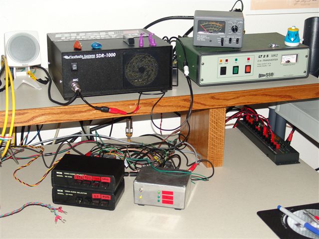
SDR-1000 as used in the June 2005 VHF Contest on 902, 1296, 2304 and 3456...It passed with Flying Colors!
The pursuit of the "Ultimate IF" - Does it exist? Well, not yet but the SDR-1000 in my opinion gets pretty close. We VHF/UHF/SHFers have some pretty specific criteria for IF radios if we could have anything we wanted Here are a few of my main requirements.
1 Frequency Readout of the actual band your on.....(This is currently in progress via software)
2 Switching from SSB to CW does not lose the signal due to frequency shift. DONE! (Works Great!)
2 Bandscope - see the actual signals. DONE!
3 Accurate control of power output. Needs work, but is workable at this point.
4 Good Filters. REALLY DONE! (The filters are awesome!)
5 Switch Bands and Control all interfaces to make it happen.....(This is currently in progress)
Which brings us the the UCB!
The UCB - Universal Control Board
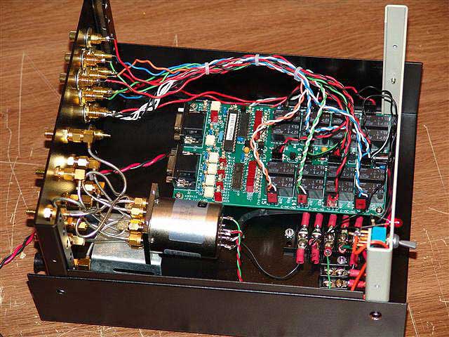
The KMØT UCB Implementation....
The guys involved with the "Friends of Flex Radio" or www.flex-radio-friends.net started talking about a controller board that could be connected to the SDR-1000, with the flexibility to make the relays on the board do switching based on what band your on. This could aid in antenna switching control as well as pre-amps, etc. However, for us microwave guys, the opportunity to switch bands on the SDR-1000 with the IF offset to show what microwave band your on via the actual frequency display, at the same time switch in the correct transverter in line was an awesome idea. This is currently in development from a software point of view. However, the hardware - the UCB itself designed by Tony - KB9YIG is already done. I had the great privilege to get one of the pre-production boards from Terry - W0VB. Terry was instrumental in the development of this hardware as well. I as am an end user, get the opportunity to put the UCB through its paces, all while helping with the ideas on how the software interface should look and feel from the microwave point of view.
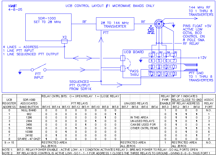
If I was to use this UCB the way I wanted, I would have to switch 144 MHz IF signals for 902, 1296, 2304, 3456, 5760, 10368 and 24192 MHz. The relay I found was a 12V single port 8 pole relay, but had 3 BCD control lines.
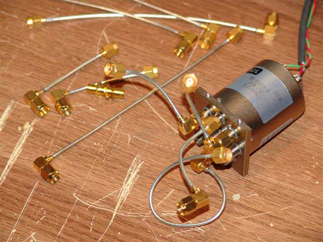
The 8-Pole microwave relay - BCD Control....
Some experimenting with this relay showed that I could switch the control lines from logical 1 to 0 simply by grounding them - as these control line would float high. And with the UCB having 16 relays, one could use 3 of those relays to do the logic switching for relay control, with plenty of relays left over to route the PTT signal. This layout even left room for one more band to add in the future.
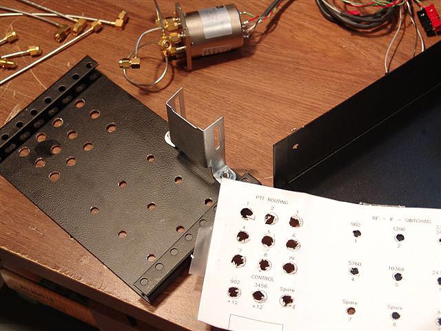
Panel fabrication and CADD generated drilling template....
From a simplistic point of view, the UCB is a relay board that has a 16x16 matrix that is controlled by software via the X2 connector on the SDR-1000. There are basically 16 ways to control 16 different relays. An interface cable between the SDR-1000 and the UCB is all that is needed. There are two connectors on the UCB, as one is a "pass-thru" connector that allows one to connect the external PTT signal into the SDR-1000. Without the UCB, one can connect an external PTT input to the X2 connector. So the UCB does not take away that functionality.
So the criteria is...
1 Switch the RF to the correct transverter
2 Route the PTT to the correct transverter
3 Do any other control switching needed. i.e. antenna switching of shared larger feedlines.
Some UCB Layout Info....
I did an Excel spreadsheets and block diagram to aid me in the design of the integration for how I wanted to implement the UCB. Here they are for review of the control scheme. Note that everything is from a VHF+ viewpoint....
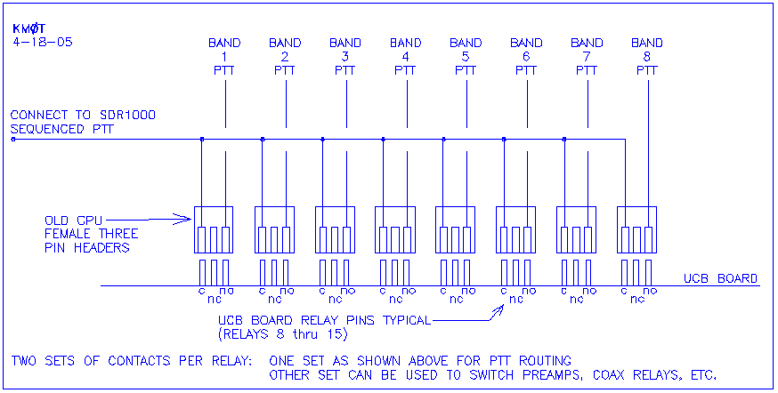
I found some old PC cable hookup wiring with pin header connectors already on the cables, those I used for wiring the PTT routing to the back panel RCA Connectors....here is a diagram of the connections.
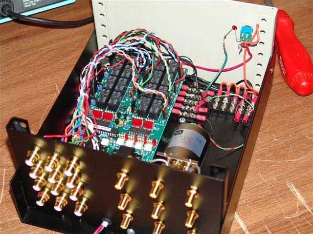
Back Panel RCA PTT Jacks and SMA Feed-Throughs for 144 MHz RF Path....
If one really wanted to "go crazy" then one could work up a way to do all the bands 50 MHz and up with the UCB. Here is a block diagram of that setup.
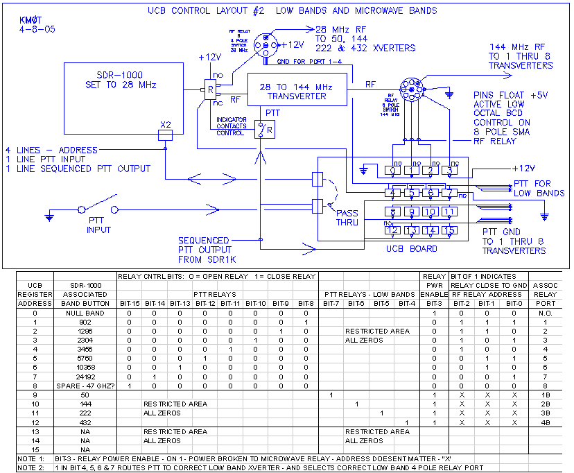
Below is the attachment method I used to keep the microwave relay on the back panel. Thus making all the SMA connections much easier. I think the bracket came from some old computer case hardware, it just happened to be in the junk box and it worked out great!
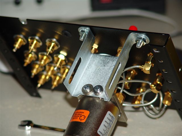
Relay attachment....
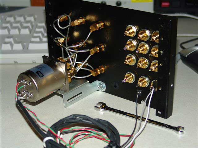
All ready to go into the box....
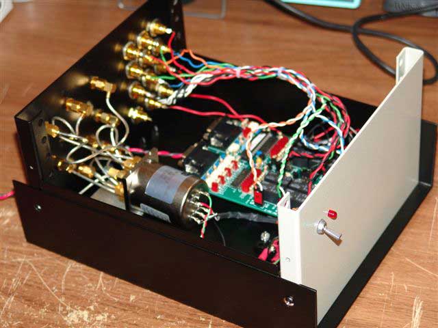
UCB Ready to Go!
Now, just to wait for the software to be done!!! GO Eric GO!
Delta 44:
The guys at Flex-Radio saw the need to have higher end sound cards to give the SDR-1000 the best performance possible. The Delta 44 card by M-Audio is a professional sound card and makes the SDR-1000 really top notch. The configuration is a bit more complicated than your standard consumer sound card, but the latency issues that are present with the Audigy 2 ZS cards go completely away when using the Delta 44.
I currently have the Delta 44 card in the box, ready to be installed. I am simply waiting until after the 2005 UHF Contest on August 6th to implement as I have things working well at the present time. Like they say, "if it isn't broke, don't fix it!" I have learned this on a few occasions, and am going to follow that advice at this time.
The above was done by July 15th 2005 at KMØT with the SDR-1000.
Preparation for ARRL 2005 UHF Contest:
I finished up the UCB hardware and integrated it into the station, waiting for Eric to come up with some software to run the whole setup. We went through a few test programs and he then came up with a setup menu after we had a few conversations on the phone and a fax was sent with a basic layout of what I thought would get me by. I really wanted to have a working system for band switching for the UHF contest, but I could live without the frequency readout for now.
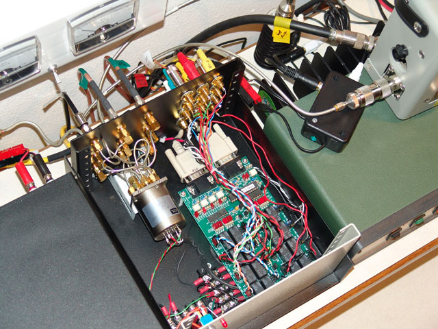
The UCB integrated into the station...
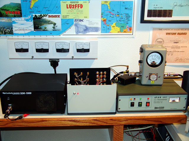
The UCB really cleans the place up!
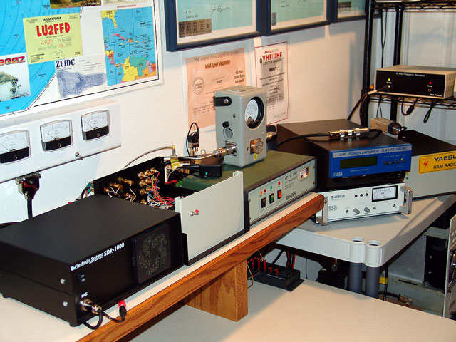
The SDR-1000 and UCB drives the 902 through 24 GHz...
PowerSDR Screen and UCB Control Matrix in Version 1.4
Note the VHF+ button below the 10 Meter Button…Version 1.4.4
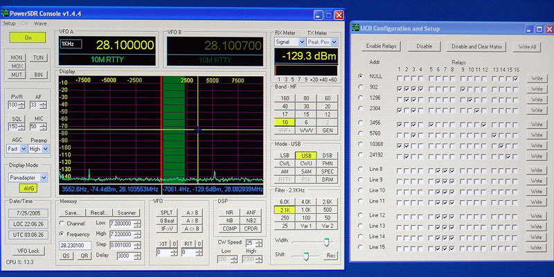
Soon the band buttons on the UCB setup menu will be on the main band switching screen when you select VHF+. The UCB setup menu will not need to be open on the screen.
Change the bands by clicking the appropriate radio button under the Addr column. By double clicking the label on the line, one can enter whatever label you want.
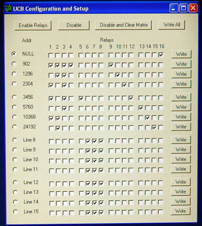
ARRL UHF CONTEST 2005:
The week before the contest, everything was working with two exceptions. I was not able to use the "X2 Sequenced Output". This sequenced output allows the PTT signal to be routed through the SDR-1000, but actually delays the transmitter from transmitting for a specified amount of time. This is allowed by a checkbox on the main setup menu.
The problem was that when I checked this box and then hit the PTT input (or MOX), the UCB relay matrix would switch back to the data programmed in the first register. Which I had only one bit selected (16). This was not the end of all my equipment, as I had a dummy load connected to the IF relay when there was no other bits selected. (note that 1, 2 and 3 are not selected for address line zero).
This caused lots of frustration as It led me to believe I had equipment problems with either the computer or SDR-1000 itself. However, swapping around SDRs, computers and parallel port cards could not really determine what was the problem. I did get it to work on the old Dell 8300, but it would not work on my Dell 8400. Very strange. In fact, I used a parallel port card in the Dell 8300, which worked...and then moved that same exact card to the Dell 8400, which did not...go figure. I had Eric at Flex-Radio very confused as well, as he could not reproduce the problem and we are still searching for the solution. However, without very many UCB boards being used out there at this time, its hard to diagnose if I'm the only guy that's having this problem. Please give me feedback on this if and when this happens!
With that I went forward and did not use the sequenced output, and just "hard keyed" the transverters at the same time I keyed the SDR-1000. Now this is not recommended for all, but that's how I had it when I used the other 28 MHz IF radios. I had transverter / amp hardware sequencing built into my high band (5.7, 10 & 24 GHz) setups, and that always worked before. So this was not a real "show stopper" but the sequencing would be a nice addition to the safety of protecting the equipment.
However the setup menu and UCB was switching the bands reliably along with the feedline routing controls when the "X2 Sequencing" was not selected. This I got working right before I had to leave for the CSVHFS conference in Colorado Springs. So I was able to put together another Power Point presentation on the UCB configuration and band switching right before I left. Terry, WØVB and myself got to do a presentation on the SDR-1000 at Central States for it's use as a microwave IF and other weak signal applications. It was very well received!
The other problem was the programming time of the UCB hardware matrix from the SDR-1000 setup menu. (This was not really a problem, just the current state of the code and UCB hardware) Eric from Flex-Radio and Tony KB9YIG were working on this and I got a new PIC chip for my UCB just in time before I left for Central States. The new PIC that Tony programmed worked very well and I was able to program my matrix in just a minute or so, compared to a much longer time when the setup matrix code was very basic and the the PIC programming was in a preliminary state. Thanks guys!
When I got back, I fired all the equipment up and got prepared for the contest. The SDR-1000 with the UCB performed flawlessly for the entire 24 hour contest and was instrumental to the success of the event. The SDR-1000 / UCB used as the IF radio for 902 through 24 GHz was responsible for 142 Grids and 273 QSOs! See my UHF / Rover Mania II 2005 write-up for all the details.
Above status as of mid August - 2005
Further UCB Implementation ideas:
Around mid August, I sent an email to Flex-Radio on my ideas for programming the UCB and the setup menu layouts. Now keep in mind that these come from the mindset of using the UCB for transverter band switching, but the ideas are generic in sense. Also, I included some text to the guys to explain the ideas of the UCB interface, as well as a few other things I thought needed attention in version 1.4. Gerald from Flex-Radio has indicated that the final UCB implementation programming is scheduled and on the list for completion in the 1.4 series.
Here is the text of the email and associated graphics I sent...
SDR Notes:
Here are some of my thoughts on how the next generation for the UCB implementation might look and feel. Other comments as well for the remainder of the 1.4 series.
VHF+ Buttons:
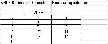
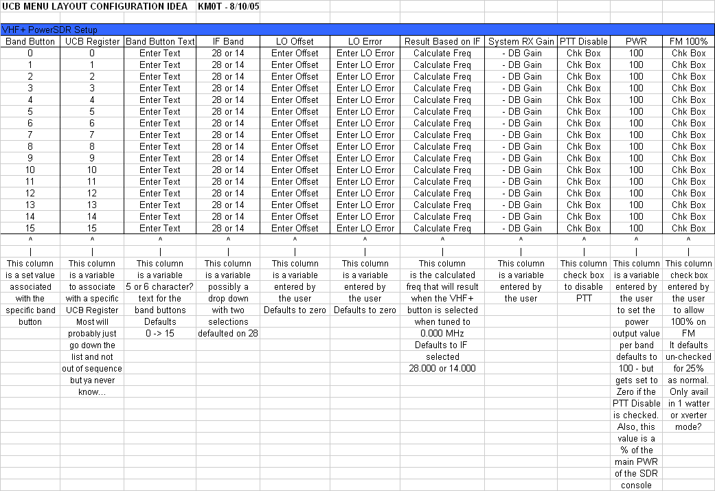
Should be a way for the user to be able to set what is shown on the buttons. i.e. 902, 903, 1296, 1297, 10G, 2.3G, 3456, 144, 47G etc.
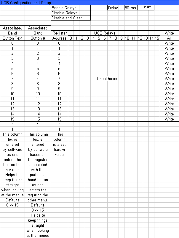
VHF+ Buttons should be able to be mapped to any register position, 0-15, of the UCB.
LO Offset frequency should be able to entered, based on the VHF+ button selected. This shall then make the overall display show the corrected frequency.
I thought about having a LO Error column. At first I thought we would not need this as it is an extra step, but rethinking it I realized that this is pretty important. As one can put in the LO Offset, which is the base to get to the proper frequency readout, then have the Error column as well. This way one can track what one puts in the LO Error column over time as the things potentially change. If the LO Offset and LO Error was to be calculated as one number, this would be a pain in the butt to track. The LO Error would simply be the + or – to the IF + LO Offset. So….
IF + LO Offset + / - LO Error = Freq Display.
I also propose a “Results” column in the VHF+ PowerSDR UCB setup. This gives a base overall calculation so that while in that setup menu, one can see the result before booting the PowerSDR Console. Would be very helpful in checking / verification that the correct LO offset and error was entered.
This frequency shown on the screen shall also be made available as valid data to logging programs, as frequency can automatically be input to the logging program.
Can we have a “PTT Disable” checkbox associated with each register address? Example if one programmed a particular register to control a receive only down-converter, one would not want to be able to transmit by accident when on that particular VHF+ button / register. So it would be a “local” PTT Disable, not “Global” like the one in the main setup menu. The “Global” PTT Disable in the main setup menus should still override as it does now.
A minus ( - ) gain figure input for receive should be available per VHF+ button selected. On transverter systems, sometime the overall system receive gain is different than from other transverters. Some are much higher than what is calibrated for correct S-meter, etc. Thus causing more noise and different band scope white noise floor levels.
Currently, I am handling this by adjusting the line in gain on the sound card, Bob says this is not the way to do it as it effects the overall calibration for RX and which in turn would screw up the dynamic range of the system.
Changing the system gain will level out the RX gains, thus making all base level white noise floor the same between bands (transverter VHF+ button bands anyway) and calibrations can be maintained for S-meter, etc. along with the dynamic range being preserved.
Register addresses on the UCB setup menu should be labeled Register 0 – 15, as these relate to binary addresses….logical Zero 0000 relates to register Zero, where 1111 is register 15. Helps to keep the confusion down, especially when register address 0000 is active, as there are no address LEDs lit up on the UCB in this state.
Relay numbers on the UCB setup screen should be labeled as 0 – 15, not 1 thru 16. 0 – 15 matches the physical relay labeling on the UCB board itself. This causes problems from the mental transition of which relay to program on the UCB setup menu verses which wires are hooked up to which relay. I know that this does not seem like a big deal, but in the heat of battle, this will be a problem. Please change this.
It would be nice to have a power output indicator for CW mode going for the 1 watt version of the SDR. Currently, this only works in voice modes.
We need to be able to adjust the power output for the FM mode for the 1 watt version of the SDR radio. Currently you have this set for 25% to accommodate duty cycle for your HF amplified version of the SDR. This equates to 0.25 watts output as well on the 1 watter, which I understand has a 24/7 100% duty cycle on the 1 watt final.
Please allow the 1 watt versions of the SDR-1000 have the ability to set the output in the FM mode via the power menu scroll box. Just as it is for CW and SSB.
See the attached excel spread sheet for possible menu setups.
I like the idea of separate setup menus for the UCB Configuration and Setup matrix, as well as the VHF+ buttons / IF frequency setup. This way one can look at them at the same time.
Thanks for your time and feedback is appreciated. This is all just my best guess.
73 -Mike – KMØT
PS – The Zero Beat function on CW was awesome for keeping drifting stations in the passband of a narrow filter!!! Worked real well on very weak signals! I was using the 250 Hz to 100 Hz filters the whole weekend! Never heard a complaint on the keyer (using external paddles with external keyer – separate sidetone from SDR monitor)
As I did the Zero beat function multiple times during the RX sequence. I was wondering if one could add an “Auto” Zero Beat button. Such as…when you get the signal tuned, you hit the zero beat button to get it centered in the RX filter passband. Then hit the “Auto Zero Beat” and if the signal is strong enough (which should not be a problem) and it changes 10 Hz or so, then automatically re-center it. It just disables when you go to TX. This would help out immensely! Perhaps there would be setting for the minimum freq change before automatically re-adjusting. Would this be hard to do?
This would work well since most of the guys I work on the microwaves know NOT to use the RIT function, we just follow each other, otherwise things get really messed up. On the Microwaves, RIT is not our friend. So, right before I went back to anyone for my TX sequence, I made sure to hit the zero beat then, that way I was right in their passband. This would be killer for sure.
Above status as of mid August - 2005
Delta 44 Implementation:
After the UHF contest, I installed the Delta 44 sound card in the Dell 8400. This made a very good improvement to the SDR-1000 setup. The transmit / receive transition times are greatly reduced. Also, the internal CW side tone monitor is very usable, as the latency is very little. However, the side tone audio level in the headphones is still a bit high, and can't be adjusted at this time. So an external CW keyer is still being used here with it's own side tone monitor. However, I know this is something that will be worked on by the software guys.
One other fine feature when using the Delta 44 is that one can connect headphones and speakers to the card output breakout box, without loading down the system. With consumer cards, when one connected these devices, it could affect the system in terms of power output. With the Delta 44 card, the audio output is a separate channel and is independent from the audio routed back for driving the radio itself.
Above - status as of end of August - 2005
UCB Software and Frequency Integration:
The Fall on 2005 resulted in the basic completion of the UCB transverter integration software. A number of beta versions came out and I tested some very specific functions of the how the UCB connected to PowerSDR. After some minor bug fixes, the software was working well! Thanks again to the programmers, mainly Eric at Flex-Radio. The actual software as it exists really looked similar to layout suggestions that I made earlier. The Xvrt Menu was also developed. This menu is what ties the hardware to the PowerSDR software. The UCB addresses can be mapped directly to a band button and frequency readout. The frequency LO offset is entered as well as LO error correction. One can label the VHF+ band buttons with any 5 characters of choice!
Shortly after the 2005 UHF Contest, I was reading all the correct band frequencies from 902 to 24 GHz, it was a very nice setup.
In 2006, great strides were made in the overall software with lots of additional features. The UCB and transverter menus have remained essentially the same since the fall of 2005.
Since then, I have been using the radio with thoughts of somehow using the SDR-1000 for my other VHF activities.
Above - status as of end of March - 2006
SUMMER OF 2006 - KMØT GOES 100% SDR:
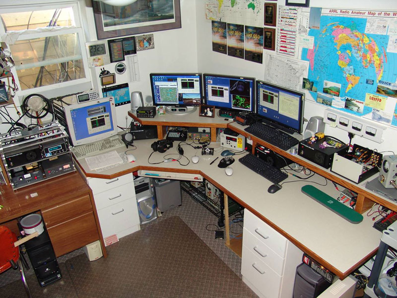
The KMØT SDR Station - HF THRU 24 GHz
The KMØT Simple 4 BAND UCB:
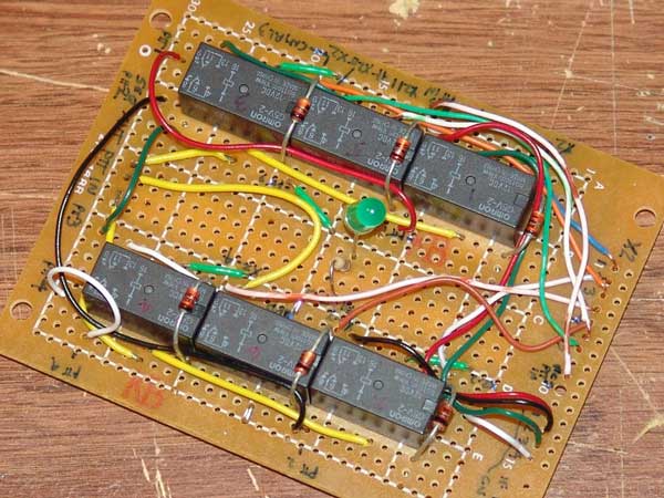
The KMØT 4 Band UCB - Simple is Good!
Between all the other things going on here, I decided to redo the station once again in early 2006, all in an effort to have SDR on all my VHF bands to take advantage of the bandscope. Wanting to have frequency readout was also a priority, but additional UCB boards were still not available. But I managed to work around this. Details on how this all went down are on my UHF Contest 2006 Writeup.
However, the main thing that made it all come together was a simple 4 band UCB that I came up with to control the lower VHF bands.
Utilizing the X2 Port Address Bits
•The X2 Port has 4 address bits:
The Basic Idea:
| X2 CONNECTOR ADDRESS BITS ON SDR | SELECT ONLY DECIMAL ADDRESS | |||||||
| DECIMAL | BIT | BIT | BIT | BIT | 1 - 2 - 4 - 8: UNIQUE STATE CHANGE | |||
| ADDRESS | 4 | 3 | 2 | 1 | FOR THE ADDRESS LINE | |||
| 0 | 0 | 0 | 0 | 0 | ||||
| 1 | 0 | 0 | 0 | 1 | CONTROL FOR 144 | |||
| 2 | 0 | 0 | 1 | 0 | CONTROL FOR 222 | |||
| 3 | 0 | 0 | 1 | 1 | ||||
| 4 | 0 | 1 | 0 | 0 | CONTROL FOR 432 | |||
| 5 | 0 | 1 | 0 | 1 | ||||
| 6 | 0 | 1 | 1 | 0 | ||||
| 7 | 0 | 1 | 1 | 1 | ||||
| 8 | 1 | 0 | 0 | 0 | CONTROL FOR ANOTHER BAND | |||
| 9 | 1 | 0 | 0 | 1 | ||||
| 10 | 1 | 0 | 1 | 0 | ||||
| 11 | 1 | 0 | 1 | 1 | ||||
| 12 | 1 | 1 | 0 | 0 | ||||
| 13 | 1 | 1 | 0 | 1 | ||||
| 14 | 1 | 1 | 1 | 0 | ||||
| 15 | 1 | 1 | 1 | 1 | ||||
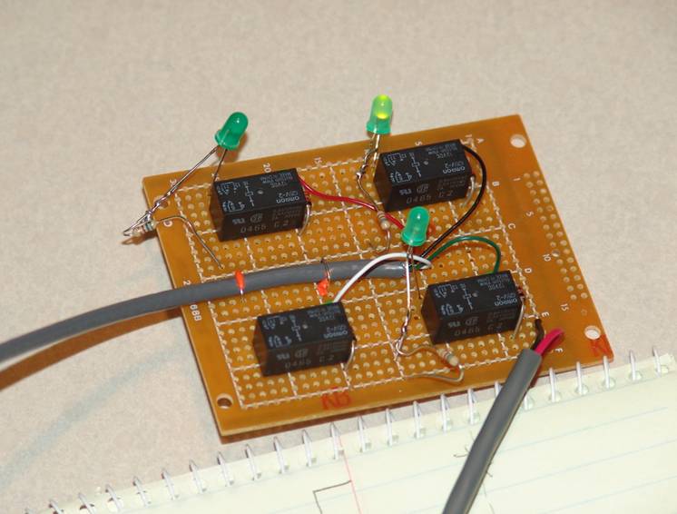
Testing the Idea - Note only one LED lights at one time while selecting the programmed VHF+ band buttons...
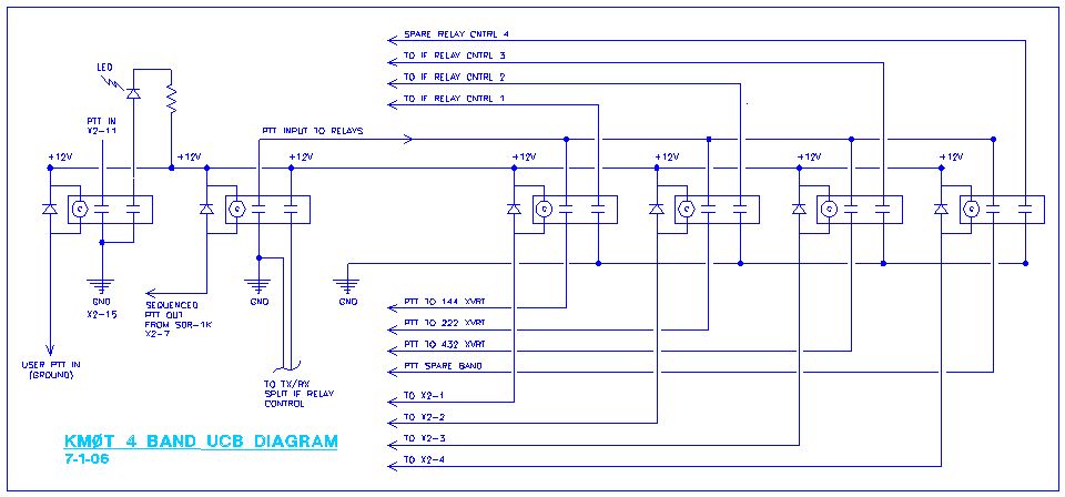
The Final Circuit Diagram Below
The Block Diagram Below
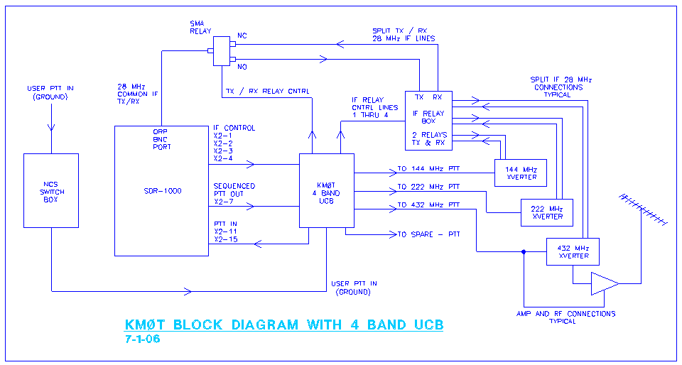
Since I had Split IF for my transverters, I had to add the relay to control the TX/RX lines.
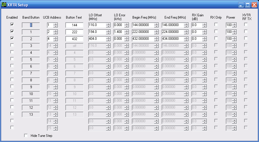
To Utilize the 4th band - just enable "Band Button 3" and set the UCB address to 8. Then fill out the band data -
Then the corresponding Band Button on the SDR screen will be available and will control the 4th X2 line.
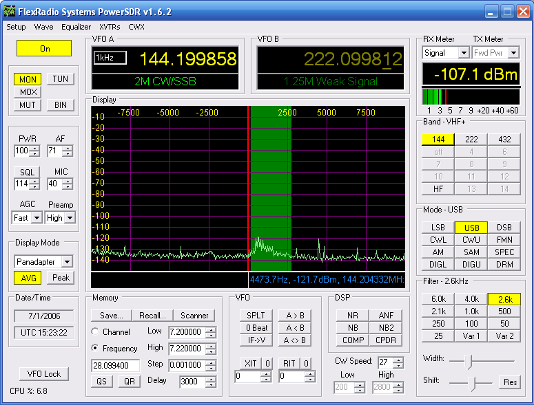
Screen Shot showing the Band Buttons and Frequency Readout - Works Great!
Above - status as of mid October - 2006
Solid SDR-1000 Modifications - Winter of 2007:
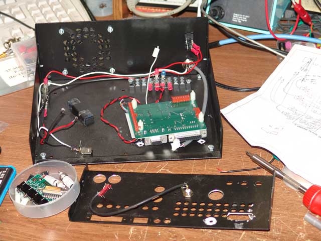
Looking kinda ugly at this point....
In the last few years of using my SDR-1000s, I have had a few things that I would have liked to have done differently in terms of hook up and interfacing into my station. Granted, I have successfully interfaced my SDRs with the station and enjoyed the benefits of the SDR-1000, but there was always room for improvement.
The first thing I wanted to improve was the weakest point of the SDR-1000, the board stack “Line-In” and “Line-Out” 3.5mm stereo jacks. Over time, these have cause issues with receive and transmit. These jacks being the weak link have also kept me from thinking of taking the SDR-1000 portable and perhaps in a rover configuration.
In addition, the other issue closely related to this was the Delta 44 sound card hook up configuration with the external breakout box and maze of cables. Various users have experienced varied results in the use of the card with the breakout box. Don’t get me wrong, the Delta 44 is a great sound card, just the implantation with the cables and breakout box is cumbersome at most, and a source for potential RFI ingress is you don’t handle it correctly. I believe this was more of an issue at HF frequencies, but I had experienced some feedback issues on 6M and 2M when the tower was lowered down closer to the house with the antenna pointed over the shack. Over time, I tried various ferrites on the multitudes of cables with no success and just lived with it.
In addition, I had many external relay boxes to interface the X2 port controls in order to isolate the X2 pins for PTT and also to provide the sequenced PTT output control to handle the transverters and amps. This configuration method required another rats nest of cables for interconnection. With that was also my version of the 4 Band UCB to control 4 transverters. This added more cables and also needed additional 12V lines for relay power and 12V lines out of it for control of external TX/RX relays for the IF lines at 28 MHz for transverter use.
As I thought about this whole issue over the past months, I started looking into the Delta 44 Breakout board by Tony – KB9YIG. According to what I had seen and read, it was a replacement for the factory manufactured Delta 44 breakout box, but added some ferrites and capacitors for RFI suppression. It also had places for installing 2 pin berg pins to jumper ground paths, this giving one the ability to test and finalize what ground paths you wanted to enable for speaker out, line-in, line-out and microphone. One could try to minimize ground loops to eliminate hum issues if they were present by jumpering the various bergs.
The few pictures I had seen of the Delta 44 breakout board and what I had read indicate that folks were still using the 3.5mm jacks from the SDR to interface with the 3.5mm jacks on the breakout board, still what I felt was a weak point.
I my thoughts gelled on the overall issues, I began to toy with the idea of taking care of all the issues with a single concept - “Put all this stuff inside the 1 watt SDR-1000”. The one caveat was that if I did this, it would make it more difficult to interface another sound cards to the SDR-1000. But for home use at the KM0T shack, I was satisfied with the performance of the Delta 44 and the band scope at 96 KHz sampling was adequate for my VHF and up operations.
Diving In – SDR #1 Prototype Modification:
My very first SDR-1000 I had was the one I was using dedicated for 6M. No UCB was needed since this was only handling one band, but a few isolation relays were needed for the X2 input and output. Those would easily fit within the SDR-1000.
I also determined that I wanted to bring the PTT input and the microphone into the front panel. This particular SDR still had the old 4-pin mic jack, so that got ripped out and replaced with an 8 pin jack. That way it would interface with the 8 pin mic connector hooked up to my NCS multi-switcher system. That cable contained mic hot, isolated mic ground and also a single PTT input line that gets brought to ground.
The board stack has a connector that cables to the back of the SDR-1000 front panel mic jack, but it was not needed whatsoever, so that was removed as well.
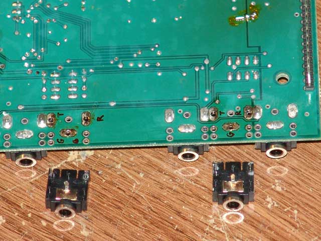
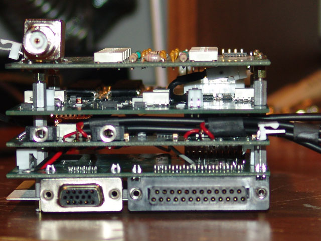
The dicey part was figuring out how to get rid of the 3.5mm jacks for “Line-In and “Line-Out”. With the board stack taken apart, it appeared that some solder wick would do the job, so I proceeded along those lines. Here you can see the 3.5mm jacks that I removed.
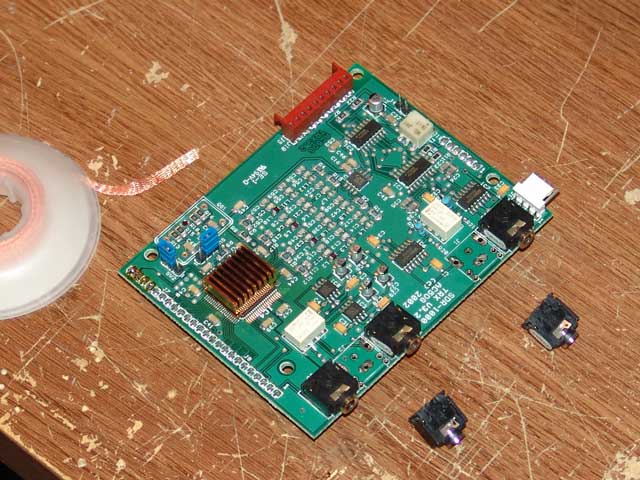
After the 3.5mm jacks were taken off, I took the ohm meter and determined where the tip and ring connector pads were located. I labeled these to help me out when I started to solder the cables on.
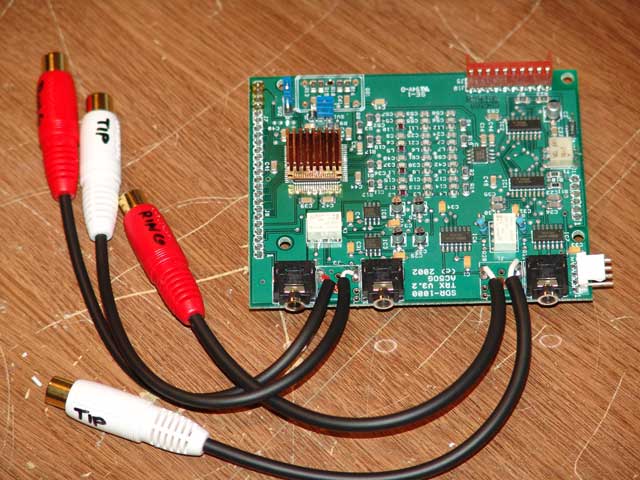
Not knowing what I was in for and thinking this was to be my “prototype modification”, I utilized RCA female jack cables. The thinking was that if I wanted to interface another sound card, I could move those outside the back panel. That is why you see I enlarged a number of holes in the SDR-1000 back panel, so the RCAs would fit through. Here you can see the cables installed on the SDR board.
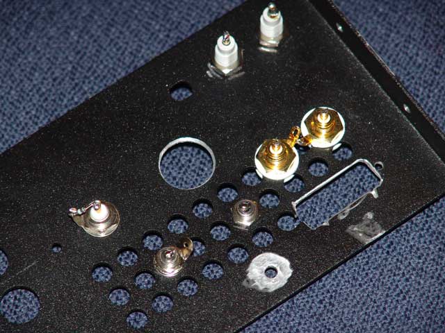
Once the soldering was done and the board stack reassembled, I started to figure out how to connect to the Delta 44 breakout board. It appeared that I could put the DB15 connector through the rear panel just by making an appropriate opening. Not good at metal work, this looked a bit crummy, but it did work. (The next SDR-1000 I modified turned out much better, see below farther down the article for details.) Also, isolated RCA jacks were installed for the speaker output. I was not sure I needed these to be isolated, but better to install them now then after the fact.
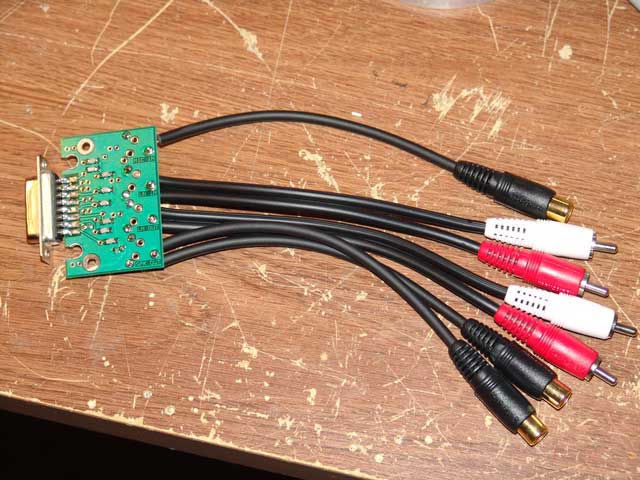
The Delta 44 breakout board just got the other side of the RCA soldered directly to the board for the “Line-In” and “Line-Out”. Then the RCA jacks and plugs just get mated.
The microphone input was brought in via the new front panel 8-pin connector and then again utilized RCAs to give some flexibility in case I wanted to hook in another sound card. When mated, the mic is connected directly to the Delta 44 sound card and does not run thru the board stack. Just like most are doing with the original Delta 44 breakout box. Then RCAs were added to connect the speaker jacks on the back panel, again for flexibility. Here you can see the prepared Delta 44 breakout board.
At that point, all that was left was to connect the interface relays to the X2 connector. I whacked the end off an old computer monitor video cable and ohmed out the connections. The back panel of the SDR-1000 was modified to allow one to lift the back panel up a bit to allow the cable to be brought into the case.
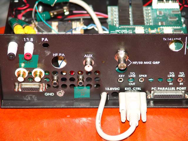
The PTT from the front panel mic jack got brought in and the X2 sequenced output was brought to an RCA jack on the back panel. I left the CW Key input jack as it was, as I have not ever experienced any issues with that.
Also, for my transverters which are split IF, one of the control relay poles also controls the need for 12V on PTT. So that connection was also brought to a back panel RCA jack. (See the previous schematic for my 4 Band UCB above in the writeup on the control relays.)
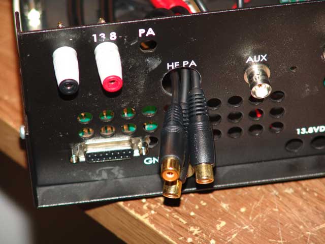
One can take the RCAs out the back panel to connect to another kind of soundcard, such as the Firebox....
During my research on the Delta 44 breakout board, one thing I found was that one gentleman just connected the ground for the speaker output. So that is what I initially hardwired. Note that I was using an older version of the breakout board, which did not have berg connections. But I got the idea of getting bergs on the board for the microphone ground from the new version boards that were currently being made. So I dug up some old junk circuit boards I had laying around and found some berg connectors and put them on the Version 1 breakout board. I figured I needed to isolate the mic ground as this has been my experience in the past. The grounds for the “Line-In” and “Line-Out” were not connected to the Delta 44 sound card via the breakout board.
As an added bonus, I provided myself with a PTT LED on the front panel from my control relays. This was just a nice added visual indicator that the rig was in PTT and that my control relays were operating correctly and the PTT was getting to the rig.
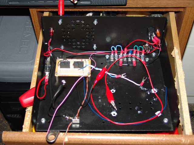
Install of the PTT Control Relays...Lots of extra room inside a 1 Watt SDR....No HF Amp needed here...
When all got assembled and hooked up, it took off just fine. The RX was good and in fact, It seemed that the pan adapter was a bit more flat, as there were less cables to pick up stray birdies and such. Upon transmit however, I had a terrible hum for SSB. I again looked over the schematic for the Delta 44 breakout board and noticed that where I jumped the berg connector next to the DB15 connector, that this was tied to the ground plane of the board, which in term connected the mic ground to the speaker ground. So I made up a wired jumper from the actual mic ground to the Delta 44 card DB15 and then directly to the mic ground berg, this took the ground plane out of the mic ground circuit and the hum was gone!
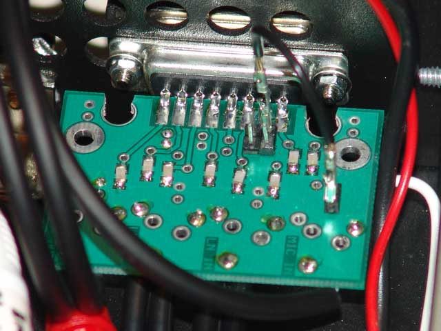
The Delta 44 Breakout Board...jumper for the microphone ground - ground plane out of circuit.
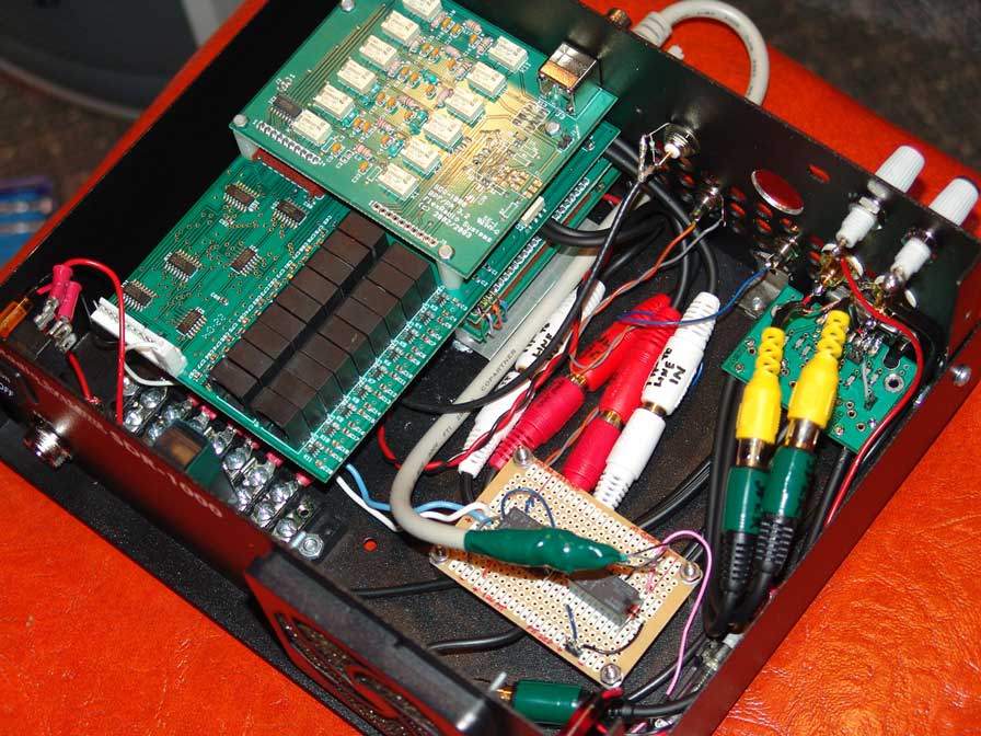
Ready to go!
Everything was working well, so I reassembled it all and put on the cover. I recalibrated the RX rejection and TX rejection and went beacon hunting on 6M! Boy did this clean up a lot of cable clutter! A few on the air tests revealed that all was working fine and I was ready to go to the next SDR-1000.
Diving In Again – SDR #2 Full Modifications:
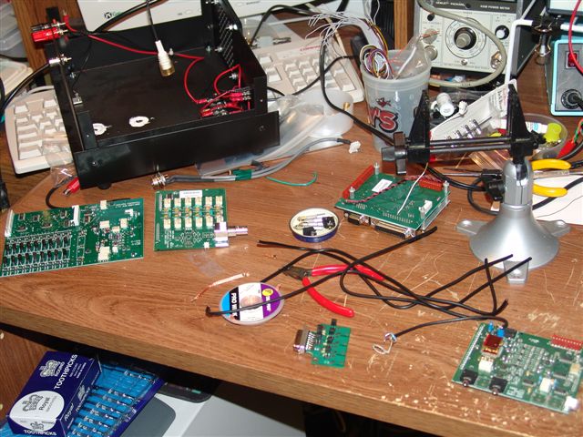
Another fine mess Iv gotten myself into.....
Now that I had successfully hacked the crap out of my 6M SDR, it was time to take a stab at the SDR-1000 which was dedicated for 144, 222 and 432 MHz. However, this time I was going to be a bit more careful on the modification, and I was not going to use RCA connector cables on the inside to make connections. I figured if I needed to modify the radio later to interface with a different sound card, I would cross that bridge when I got there. Also, I decided to build another KMØT 4-Band UCB, as the one I had been using was all outfitted for external connections, so I figured I would keep that around for a spare.
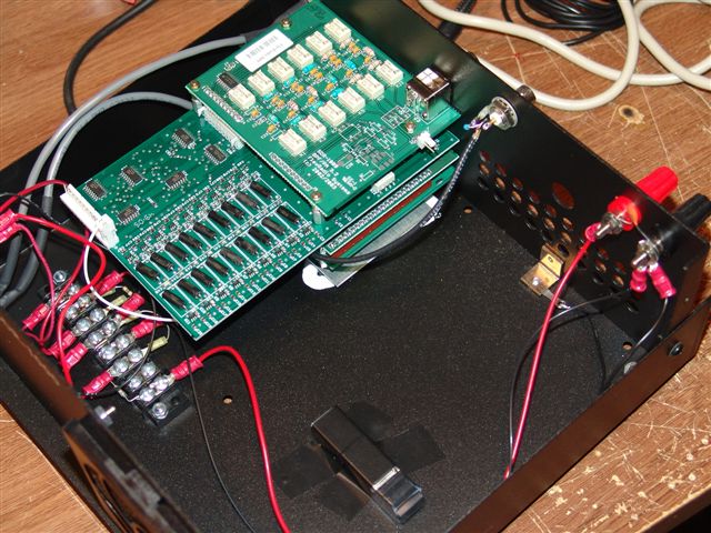
Ready to take apart....
I first started with the back panel, drilling the holes out a bit for the isolated RCA jacks for the speaker out L and R connections. I then decided that a better spot for the DB15 connector for the Delta 44 cable was a bit below the vent holes. I started by drilling two holes for each side of the connector.
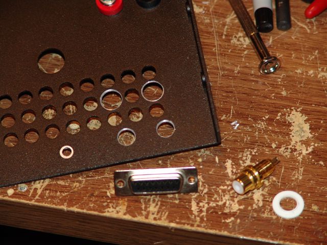
At that point, I used a Dremel tool to cut the horizontal lines, it worked out very nicely and looked a lot better!
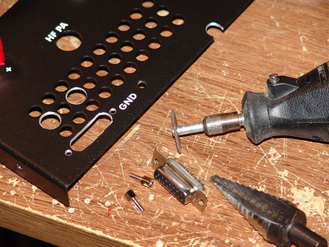
A little more time and thinking made a much better hole for the DB15. Note the cut on the bottom of the back panel for the X2 Cable....
I then assembled the Delta 44 breakout board. I purchased some new version boards from Tony - KB9YIG. These new boards come with the ground jumper bergs. I soldered directly the speaker grounds, but put bergs in the rest of the spots to make sure I had total flexibility. I then jumpered all of them by default.
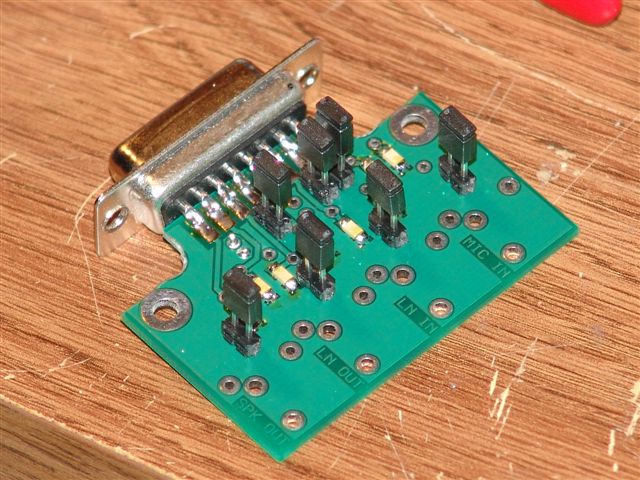
Delta 44 Breakout Board - Version 2.
I again took apart the board stack and installed the cables after wicking off the "Line-Out" and "Line-In" connectors. I used a thinner cable this time and it seemed to work out much better.
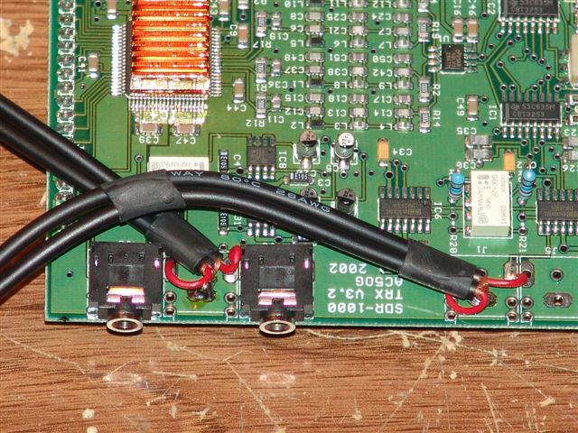
With the thinner cables, they fit a bit better between the boards.
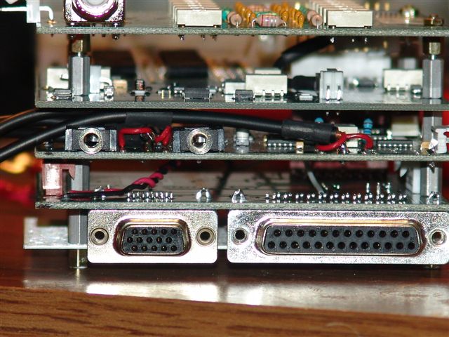
Board stack showing the direct cable connections....
The cables then were attached to the Delta 44 breakout board.
The breakout board and SDR board stack got all installed. The RCA jacks were also installed for PTT control, and IF relay control and the split IF transverter TX/RX relay control.
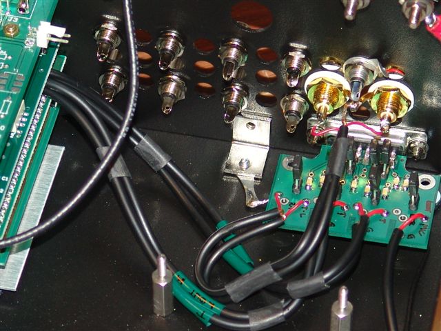
Looking much better for sure!
I then located another VGA cable and prepped that for connection to the new 4-Band UCB. 7 lines are needed. X2-1 thru X2-4 for addressing, X2-7 for sequenced PTT output and X2-11 / X2-15 for PTT input.
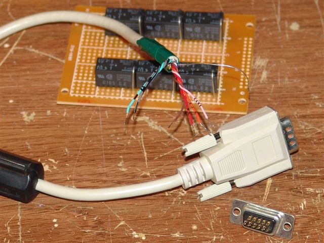
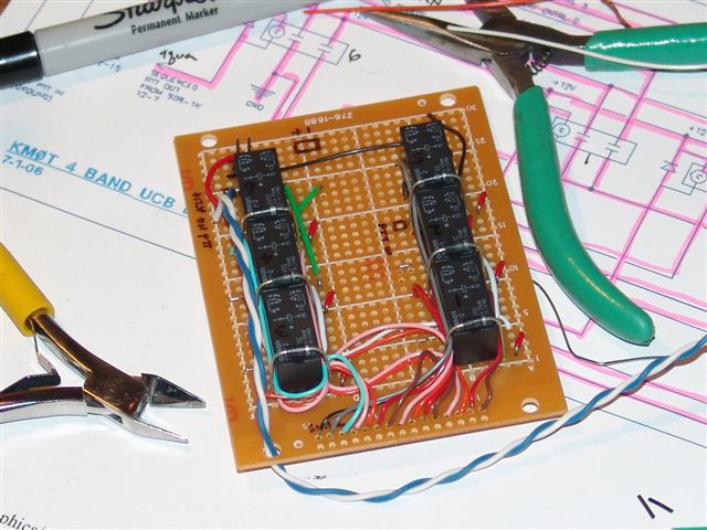
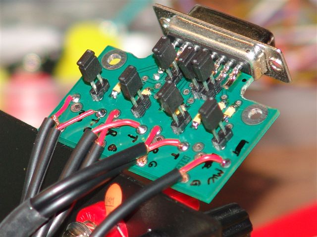
The newly completed 4-Band UCB...
I then gave thought to some additions to the UCB. I added a connection for a PTT LED and also a variable voltage regulator. This I used to power a fan and being adjustable, I could make the fan speed lower so it did not produce a high noise level.
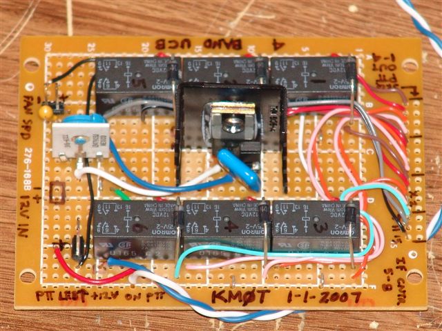
The newly completed 4-Band UCB...with the bergs, labeling and LM317 - It worked awesomely!
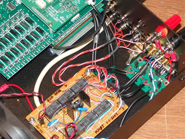
All parts installed and connected - it fit very well! Looks clean too!
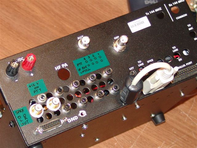
Back panel labels....the weak point of my modification...I need something better!
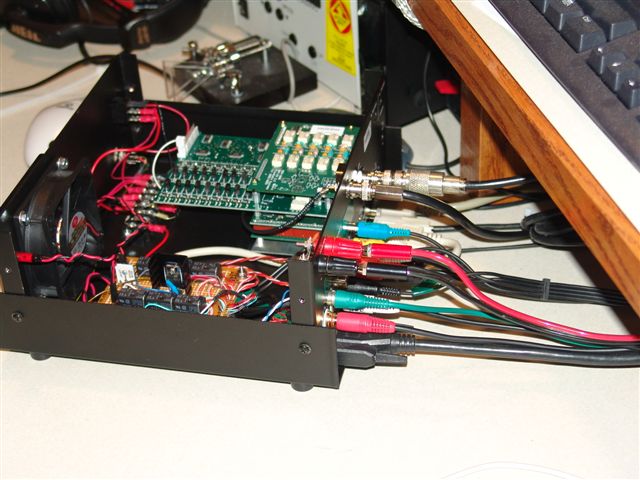
Nice and clean! See the Delta 44 cable directly connected to the SDR-1000.
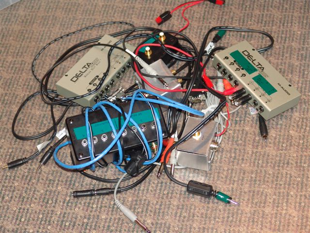
Pile of cables and junk the above mods eliminated - it really cleaned things up!
The modifications worked out great and as expected. The newly constructed 4-Band UCB worked flawlessly and again, I believe the mods provided for a reduction in birdies in the bandscope by eliminating multiple points to pick up those signals. The RFI was gone too. I could not tell any difference when I had the antennas pointed over the house while running higher power or when they were pointed away. Also, I never had to change any jumpers on the Delta 44 board, as I had no hum issues whatsoever, even with them all jumpered.
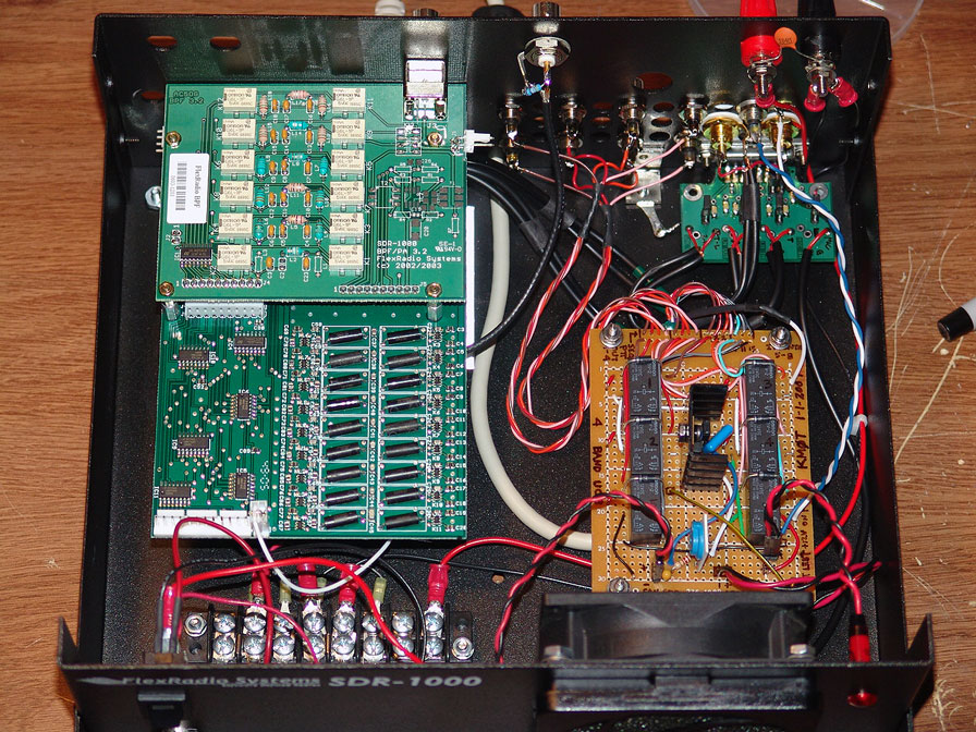
Larger view, it worked out really great!
With the above mods, I would have no reservation about taking my SDRs roving or portable, now to figure out how to get a few computers in the truck!
The mods will be done in due time to my Microwave and HF SDR, althought there will be slightly different approaches. Especially for the HF SDR-1000 as the 100W amp takes up all the space I am looking for. I'm thinking the Delta 44 breakout board can be mounted above the board stack near the 2M transverter holes already drilled in the case. That way the cables can be routed around the other side of the board stack to get to the "Line-In" and "Line-Out" connections. We shall see when I get time to work on this.
Long live the 1-Watt SDR-1000! Hands down the best VHF+ Transverter IF available!
Above - status as of mid January 7, 2007
Three Times a Charm – SDR #3 Full Modifications:
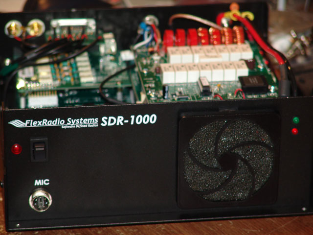
Modified HF SDR-1000...
After SDR-1000 #2 got modified, I worked with it for a few weeks and was very pleased with its operation. I then decided to tackle the HF SDR-1000 that also included the 100W amp and LDG tuner. I removed the SDR-1000 from the custom rack I had built and took off the rigs cover. I stared at it for about a ½ an hour wondering….”should I tear this thing apart or not…..”
Well, my wife had taken the kids away for a long weekend to go visiting, and I was home alone. The more I thought, the more I knew this was the time to do it as the modification work would have my undivided attention. So, out came the tools and the next thing I knew, I had SDR parts scattered around the shack.
Again, the first part was to remove the “Line-In” and “Line-Out” jacks from the I/O board. Some forward thinking led me to believe that the Delta 44 breakout kit could mount above the board stack near the transverter holes. So, I opted to run the cables the opposite direction from the jack holes than when I had modified the 1 Watt SDRs.
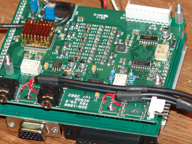
Line In and Line Out Cables soldered on....
Cables Exit "Stage Right"
The Delta 44 breakout board was assembled and then put up to the back panel to eyeball where an optimum location was. It appeared to be about half way between the closest transverter port hole and the QRP BNC hole. Just be sure it’s low enough so the SDR-1000 cover does not keep you from putting the Delta 44 cable to it. The hole got cut in again by drilling holes and using a Dremel tool.
Back panel ready for Delta 44 Breakout board to be installed...
As this was an HF SDR, all I needed (at this time anyway) was a few relays to isolate the PTT in and get the X2-7 Pin for sequenced PTT output. I wondered where those relays could be installed, I was pretty much out of room. A bit more staring at the whole mess revealed that there was plenty of room under the RFE board. Hey, that was pretty sweet. So, a little measuring and laying the circuit board on the case bottom as a test was all that was needed and the holes for the standoffs got drilled.
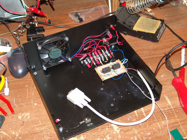
Relay board that will fit below the RFE board...
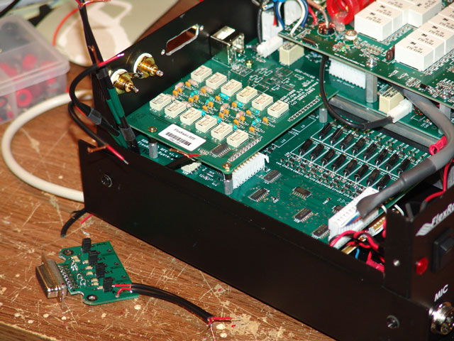
I again removed the mic input jack on the back panel and also the connector that brings in PTT to the board stack. The PTT from the mic jack to the board stack is useless for me as it only mimics X2-10 for PTT, which is for voice modes only. So on all my SDRs, this cable got removed. (X2-11 again is the “All-Mode” PTT input) The mic connection from a new front panel mic jack got connected directly to the Delta 44 breakout board.
The PTT relay board got installed and hooked to power. I connected the line for X2-7 sequenced PTT output to a RCA jack. The hole left by taking the “mic-in” jack out was just what I needed! I also put a PTT LED out on the front panel next to the switch. This I connected to the X2-7 controlled relay, so it will light even when you hit the MOX button on PowerSDR, assuming you have “Sequenced X2” enabled. (I think I did this wrong on the other SDR-1000 mods, as I hooked the PTT led to the first relay. Well, if you don’t do a manual PTT input, then the PTT LED won’t light…oops!)
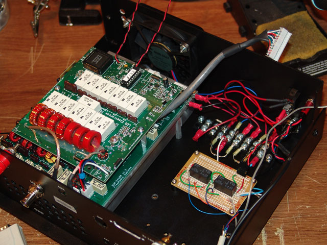
100W Amp and tuner installed next to the relay board....ready for board stack...
The transverter port holes were just the right size for my isolated RCA jack, but since they were not “round holes” I needed to ream them out a bit, then all was well and the isolated RCA insulators fit just fine. These again were for the “Speaker Out” L and R.
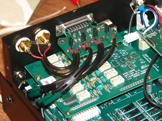
Delta 44 Breakout board installed and wired....above the board stack...
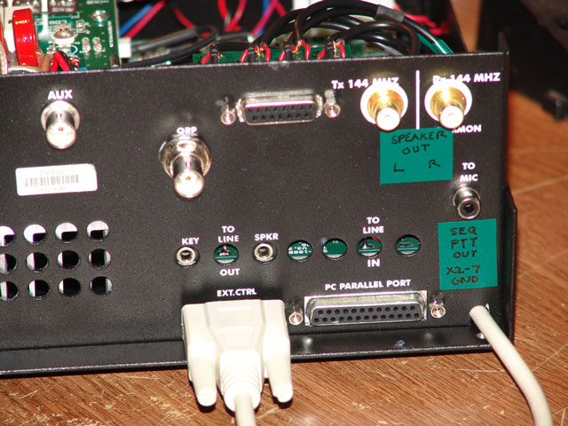
Back panel showing the modifications...
Note the Sequenced PTT output at the original mic jack location...
Another old VGA extension cable was found for use. While ohming this out, I realized that the conductor for X2-15 was not there! So, all I had was X2-11 and X2-7. Well, according to my diagram, when one grounds X2-11 to X2-15, that puts the rig into transmit. Well, without X2-15 available, I just brought the other end of the relay contact directly to ground. Not a big deal. Not all VGA cables are created equal!
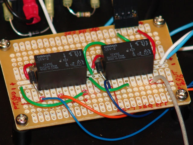
Relay Board...
I then recalled guys on the reflector talking about the LEDs for the tuner being inside the rig. Well, out came the soldering iron and I took these off the board. I pretty much ruined these LEDs while doing this and ruined one of the plated thru holes. Whoever installed the LEDs bent the leads over pretty tight before soldering and as I was pulling them out, the lead pulled out one of the plated holes. Use plenty of heat and solder wick, then re-bend the leads before pulling out! I was able to repair it all and actually got the plated hole via back in the board without breaking the trace that had pulled off the board!
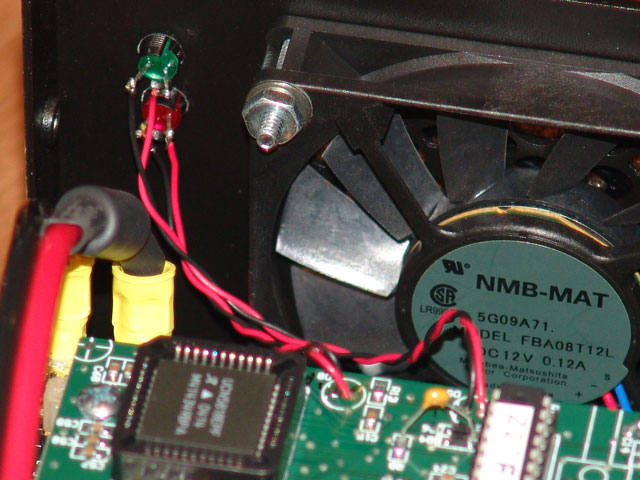
Tuner LED Mod...
It was a neat experience taking the ATU board off of the amp and being able to take a close look at the amp construction. Very nice indeed! While doing this, I noticed one of the plug-in RF cables between the amp board and the ATU board had some stray ground braid coming off of it. These few strands of braid were actually touching the wires wound on the toroidial inductors. Well, I wonder if that ever affected anything. Anyway I got that cleaned up too.
I hooked up all the loose wiring and put the rig back together. At that point I connected the Delta 44 board up and screwed onto the back panel. It all came together very nicely. The SDR-1000 got mounted back into the rack and I fired it up. I was very impressed. Now I don’t have any quirky operation from stray RF floating around and getting consistent power output from my Ameritron solid state amp on all the bands. With the SDR at about 30 to 50 on the drive level, I can get 3 to 400 watts on the higher bands while I’m getting 400+ on 80 and 160M. Very nice indeed.
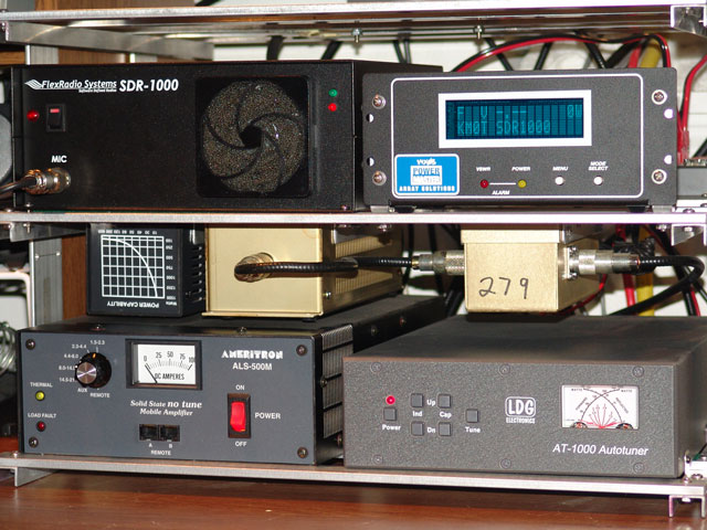
Complete HF station with Wattmeter, Linear, Tuner, Dummy Load and Low Pass Filter...
Oh, those LEDs for the internal tuner work great too! I had wondered if mounting the Delta 44 board inside the 100W rig would present a whole new mess of problems, like feedback or RF in the mic circuit, but on the air tests running a good load of power resulted in no complaints. In fact I got “Hey, that rig sounds really good!”.
The only thing left to do for the HF SDR-1000 is to put in a temperature controlled fan speed control. I have the kit to do it, but just need to get around to it. The next SDR-1000 to modify will be the one the drives my microwave equipment, but the January 2007 VHF Sweepstakes are coming up very soon and I have learned in the past to not dive into something right before a contest!
Above - status as of January 15 - 2007
Hope the above info was helpful...
CUL and more to come...
73 de KMØT EN13vc