The KMØT 5.7 and 10 GHZ Project:
Introduction:
After good success with the 2.3 GHz and 3.4 GHz set ups, I decided to give it a go on the higher bands. I had always had an interest in 10 GHz as the members of the Northern Lights Radio Society (NLRS) had quite a bit of experience on the band and were always fired up about it. I really didn't have any idea what to expect.
At the end of June 2001, Donn – WA2VOI came to Sioux Center and brought some portable 10 GHz equipment. We were going to try to work some contacts to get some states for the CSVHF "States Above 50 MHz" event. He brought his own equipment and an offset DSS dish setup he borrowed from Gary – WØGHZ. Also, Jim – KØMHC was there to lend a hand and give me some moral support since I had absolutely no experience on 10 GHz.
With Donn’s careful planning and mapping some paths with the "TOPO USA" software, we managed with little effort to work 3 states on 10 GHz, Iowa, Minnesota and South Dakota.
I sat on my rooftop with the 10 GHz setup and brought my old Kenwood TR-751 up to the roof for 2 Meter liaison. It was a super hot day and being on the roof did not help matters much in that regard. Donn gave me the maps and told me where to point. When he got to his operating positions, he was always right on the beam heading as he said he would be. It was really neat and I also got to move the dish around a bit, both in azimuth and elevation, just to see how sharp the beamwidths were. Plus or minus a few degrees and bam, he was gone!
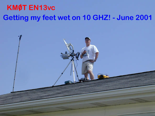
It was a very good experience on 10 GHz and it really got me "Hooked" for thinking about getting on the band. Not to mention that the 3 extra states for CSVHF made the difference between first and second place for the event. Thanks Donn and Gary, I really owe ya!
Overview of the Equipment:
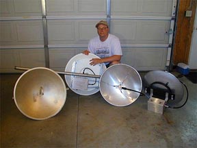
I first began by looking into antennas. I recall coming across a 10 GHz dish on ebay. The dishes were commercial made by MACOM and appeared to be a good value. The interesting thing about this dish was that it had a buttonhook waveguide feed, virtually no loss. I put out a few e-mail's about these dishes to the VHF reflector as well as asking the person who was selling them about their performance. I got pretty good feedback and decided to go the ebay route to get my first high band dish. As a matter of fact I ordered two dishes so I could have a rover set up as well. They say there is a 24 GHz feed for the same dish, but I have never come across one. (If you have a spare 24 GHz feed for these dishes, please let me know!)
About the same time, I began looking into dish solutions for the 5.7 GHz band. There were not a lot of options out there, but David at Directive Systems had 60 cm (~2 Feet) dishes for sale with copper pipe feeds. Around the same time I was looking at these dishes, the Northern Lights Radio Society (NLRS) was having a club group order with David at Directive Systems. So, I ordered two of those dishes with copper pipe fees and the respective mounting brackets.
With the antenna portion covered, I began to look into the transverters for those bands. I had good luck in the past with DB6NT transverters on my 2304 and 3456 MHz systems. So I ordered the 5.7 and 10 GHz versions. I shied away from the kits, as I had little to no experience in building these. It appeared that these were for the experienced builder.
I also began to look for power solutions for these bands. Many folks were running just the bare transverters with no power amplifiers, and were having good luck. I figured a bit more power would be a big advantage. Having dealt with the DL2AM amplifiers on 2.3 and 3.4 GHz led me to look for the same brand for 5.7 and 10 GHz. Due to time constraints to get ready for the June 2002 Contest, I decided to order these through Gerry and SSB Electronics.
I also needed a way to get these up a bit above ground, so I looked into a new tower solution.
I researched all kinds of tower configurations, even fold over types but found that Rohn wasn’t making that anymore. Then out of the blue, Gene – NØDQS found two old Wilson MA-40 crankup masts with rotating bases in Rochester Minnesota. We cruised up there one afternoon with a boat trailer and bargained with the guy. We ended up bringing them home for $325 apiece. Not a bad deal, they were in good shape. A call out to US Tower got me the tower base bolts for a bit over $100 and I began to plan on digging the concrete base hole.
In late October and early November, the base hole was dug and I began working on the rebar cage and grounding. Also made the bolt template and got things all put together to wait for the concrete. See the June 2002 Contest write-up for details on the tower installation.
All the parts were pretty much in place, except for the amplifiers, they would take a bit to get out of Germany. I integrated them into the system as they arrived. The following is a semi-technical description of the building and setup of the KMØT 5.7 and 10 GHz station.
Equipment Boxes:
After having a bit of experience in building this stuff, I tried moving everything to a modular approach. Using common IF input, RF output connectors, common power and controls connectors, common mounting methods, etc. This way one could switch the boxes out and replace with another. The plan was two build two sets of 5.7 and 10 GHz boxes, each "band box" identical. One set for a rover setup and set one for the home station.
The first step was to obtain the equipment boxes. Hoffman seems to have the best selection of aluminum weatherproof boxes, although a bit spendy. However, Matt, KFØQ was able to get these boxes for me through his work and the cost was not too bad. The aluminum is great for drilling holes, its lightweight and looks good, no rust! The weatherproof capabilities of these boxes are also a great advantage. Thanks Matt!!!
The Hoffman catalog number of the boxes I used is A-8064CHAL. Its dimensions are 8x6x4.
Input / Output Connectors:
Each "band box" design has a single IF connection for 144 MHz. This and the RF output consist of 4 hole bulkhead SMA to N connectors. These are found on ebay from a number of sellers. I sorted the quality of these for using the high frequency rated units for the RF output, and the lower quality units on the IF side. I am told that if you look into the N connector side of these bulkhead adapters, look at the pin and see how many "legs" make up the total pin. Most have 4 "legs", the lower frequency version. The higher frequency models have like 6 legs, and fit the mating cable pin "tighter" or with more precision; thus rated at a higher frequency range.
The power and controls connection is made up of a multi-pin composite connector. The connector can hold 16 pins (not that I need that many) and both male and female versions are needed. The one that mounts on the box has a 4 hole bulkhead flange mount. All power and control conductors are combined under this same connector.
Then one orders the gold plated pins, male and female for as many connections that are needed. After soldering on the conductors, the female pins are inserted in the bulkhead side for the box mounted connector. The male pins are for the umbilical connection cable. The connector bodies and male/female pins were obtained from Digikey.
So, for each "band box", there are only three connections through the box, IF, RF and Power/Control.
Dish Mounting:
For the 10 GHz dishes, I used some of the adapter aluminum that came with them, then some galvanized angle iron for getting mast clamps attached. A WR-90 waveguide adapter bolts to the button hook feed horn from the backside. A small length of 3/8 superflex was used for the connecting cable. I believe it is about 18" long. These factory made cables are readily available on ebay for a reasonable price.
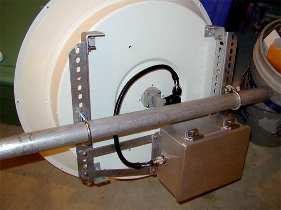
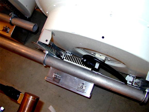
The 5.7 GHz dishes have a ring mount for attaching to the mast, however I had to fashion adapter brackets out of some steel strap for mounting the band boxes to the entire assembly. The brackets offset the box from the back of the dish to make room for the heat sink.
Again, 3/8" superflex was used. John, KØPW made these cables for me since I was in a pinch for time and he is very good at it! They worked out very well and made the 5.7 GHz systems work great. Thanks John!!!
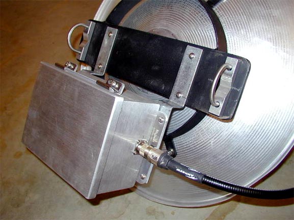
Below, see the heat sink on the backside of the 10 GHz box. The angle iron offsets the box to enable room for the heat sink.
"Band Box" Layout:
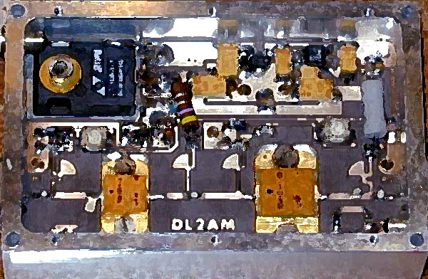
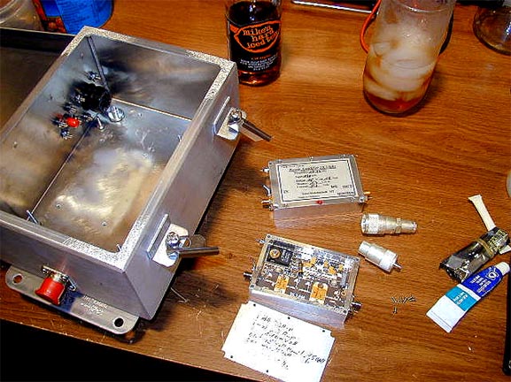
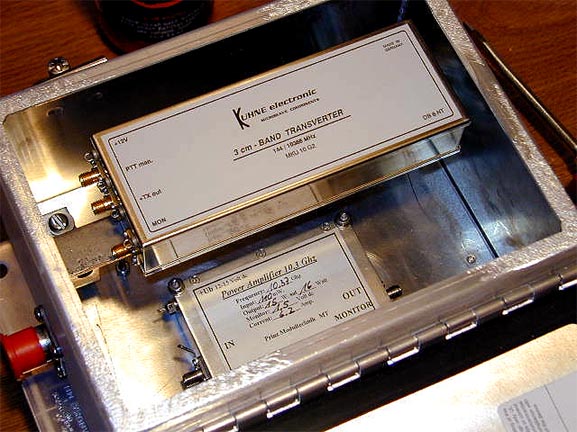
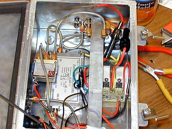
Quite a bit of time was spent on figuring how the amp and transverter would mount inside the box, as well as where the relay and bulkhead adapters would be located. After many mockups of the physical layout, my Dad fabricated a special mounting bracket from simple strap iron and some "L" shaped shelving brackets. We brazed the "L" brackets to the strap iron, and screwed the "L" brackets to the internal stand-offs in the box. Here are a few pictures early in the construction process. The 15 watt DL2AM amp is shown, note the size in comparison to the RF connectors shown for a reference.
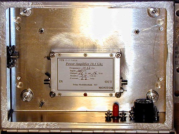
Shown below, the amp mounted to the inside of the box.
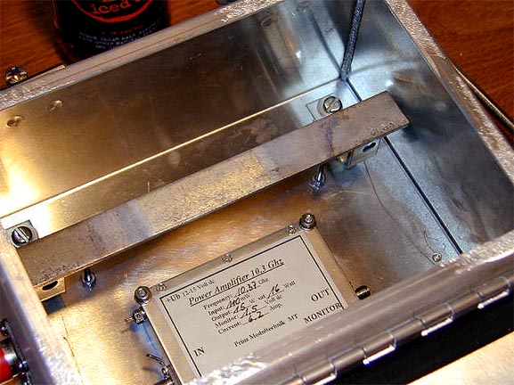
Shown below is the "L" bracket screwed to the inside of the box using the boxes standoff mounts.
Below, the transverter and amp showing the approximate layout.
Heat sink material was obtained from ebay and then cut to an appropriate size, mounted to the backside on the outside of the box. Mounting holes for the amps were then drilled through the Hoffman enclosure and heat sinks for mounting the amp on the inside of the box. Once the screws were tightened over the course of a few days to squeeze out the thermal grease, the outside edges of the heat sink and screw penetrations were sealed with silicone. Long stainless steel machine screws were obtained from a local "True Value" hardware store which had a very good selection in comparison to many others I checked with. All the bulkhead RF and Power/Control adapters were also sealed with silicone.
"Band Box" Wiring:
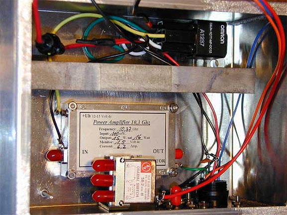
The SMA relay was mounted on another "L" bracket which was bolted to the side of the enclosure. Below you can see wiring as it comes out of the multi-pin connector. The first version of the internal wiring was such that on PTT condition, the "Omron" power relay was used to control the 12V DC to the DL2AM amplifier. These linear FET type amplifiers draw their full current whether or not there is any RF drive, so the +12V is only connected when they need to operate. When PTT is active, then +12 is delivered to the amplifier. Well, this was the same exact connection scheme I used on my 2.3 and 3.4 tower box project. That equipment has been working flawlessly for a few years, so I decided to go with the same scheme.
However this turned out to be a very very big mistake. When the project was all done and things were all set for the June 2002 Contest, it appeared that both sets of 10 GHz boxes could not really hear anymore. Tons of scrambling around did help matters much when I was trying to diagnose the problem. So these high band boxes could not be used during the contest. Gene and I only managed to work each other when he was right in the neighborhood. Note that the amplifiers for 5.7 GHz never showed up in time, so the following is for the 10 GHz setups.
Some asking around and investigation reveled that the front end gasfets on the RX side got toasted. The relay isolation, or "hot keying" was what ended up being the issue. As recommended in the DB6NT transverter documentation, sequencing the amplifier was recommended. I however never gave it a second thought since I had used the same setup and power relays on 2.3 and 3.4 GHz with no issues. Still not sure why, but the isolation at 10 GHz must not be enough or these high band 10 GHz transverters were more sensitive to "hot switching". DB6NT indicates that relay "uncoupling" should be approximately 50 dB. Power on the input device cannot exceed 1 mW.
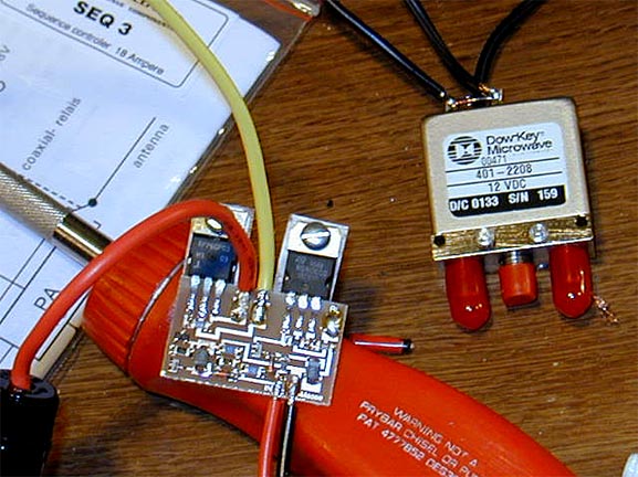
Below, here is an electronic sequencer. Note the size in comparison to the SMA relay. (These 12V SMA relays are pretty rare, but I found some on ebay for $25, what a steal!) Anyway, DB6NT makes the sequencers in 3 different versions, switching small to large amounts of current. The SEQ 3 version switches up to 18 amps and must be heat sinked. So, the power relay stuff was torn out and the sequencers were put in.
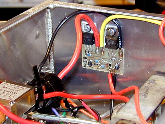
One version below shows the sequencer mounted to the side of the box as the heat sink.
On the other, I mounted the sequencer to its own heat sink and mounted it in the bottom of the box. I decided to do this two different ways, just to see which way worked out better. (To date, neither have posed any issues) Now the sequencer basically is keyed on PTT and delays the +12V to the amplifier in order to let the SMA relay time to switch from RX to TX before the big power comes out. When PTT is released, the +12V to the amp is removed first, then a delay before the SMA relay switches from TX to RX. This in essence protects the front end RX gasfet in the transverter. Delay time on the SEQ 3 is 100 to 150 mS both directions.
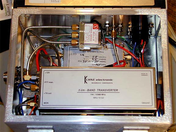
Below is a close-up of one of the completed 10 Ghz "Band Boxes". Tie straps are used to secure the transverter to the "L" bracket standoff.
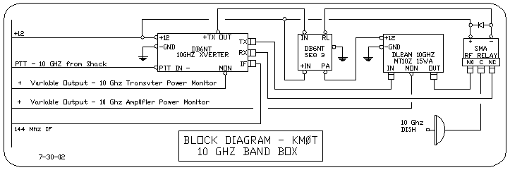
Here is a block diagram of the 10 GHz Band Box.
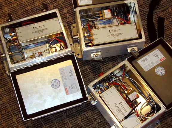
Below are the two 10 GHz boxes and one 5.7 GHz box, again no amplifiers in the 5.7 GHz boxes at this point.
"Band Box" Tower and Rover Installation:
With the dishes completed and ready for install. Gene - NØDQS was to have a set mounted on his rover, and I had finished up installing a MA-40 crankup mast. See the June Contest 2002 write-up for details on the tower.
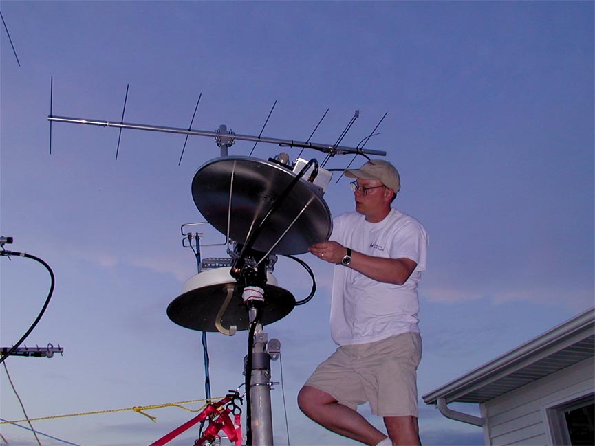
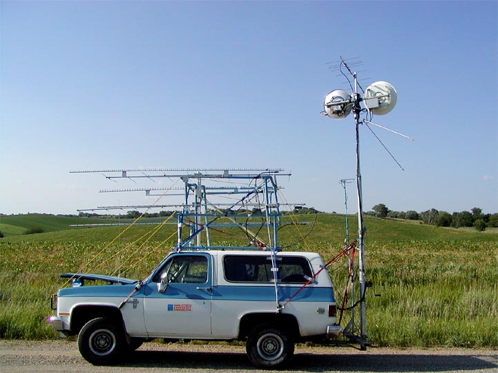
Below are a few pictures from Gene's Rover installation. Here is yours truly installing the 5.7 GHz dish and "Band Box". Note the "Button Hook" feed on the adjacent 10 GHz dish. These dishes were mounted on a custom crankup aluminum tower the Gene built. The rotor was a Yaesu G-5500 AZ-EL rotor in order to rotate the dishes to a totally horizontal position in order to reduce dramatically the wind load when in transit. In addition, the AZ-EL system allows Gene to not worry too much about exactly where the rover is pointed or if he is on a sloped road. A bit of tweaking and one can get the dishes on horizon and pointed in the correct direction. We have found that the beam width issue and resolution of the rotor has not been a problem. Sometime we just have to hunt around a bit. The 222 MHz yagi rotates as well in azimuth and we have used that for peaking. One way I do that is I sent him a CW beacon or carrier, very very low power and he just peaks up on me. Most of time that works pretty well.
Below is Gene's Rover for final fit out. See the dishes in horizontal fashion. The crankup mast is up just a bit from its nested position. See Gene's website for details on the crankup mast.
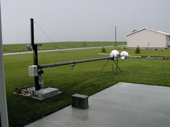
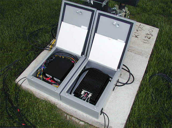
Below is the MA-40 crankup mast laid over on its side to allow the dish installation. The two boxes on the base are for a DC power supply to power the "Band Boxes" as well as a 146 and 440 FM amplifiers. The VHF and UHF FM yagis are not yet mounted on the cross boom. The DC supply is powered from an outlet in the shack. I just plug it in when I want the gear to be powered up. However, I have a few switches in the shack which control power relays, where I can switch the "Band Boxes" and the amplifiers on separately. The aluminum box on the back of the tower base is for coax lightning protectors to be housed in. All the cables, power, RF and control run back to the shack in a corrugated 4" drain tile pipe I had dug in before I planted the grass. 100 feet of that stuff was only about 20 bucks at the local home depot type of store. I considered PVC, but boy was that expensive, plus not too flexible. The cable pulls just fine in that corrugated drain tile pipe. ( I used the version that does not have the drain holes ) Again see the June 2002 Contest write-up.
Below is a close up of the interiors of the equipment boxes at the base of the tower. The DC cable just runs up the tower with the RF cables. Voltage drop calculations were done in order to size the wire, I ended up with #8 AWG. The IF cables to the transverters is LMR-240F - the flexible version and same size of RG-8X, made by Times Microwave. These cables transition to LMR-400 at the tower base, which is run back to the shack in the drain tile pipe.
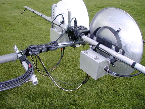
Below is a close-up of the cross boom with the G-550 elevation rotor. Again, I turn these dishes horizontal (dishes pointed straight up) during windy conditions, they have survived 58 MPH so far (with the tower nested!) One can see the cables off to the end of the cross boom to pick up the VHF and UHF FM yagi feeds.
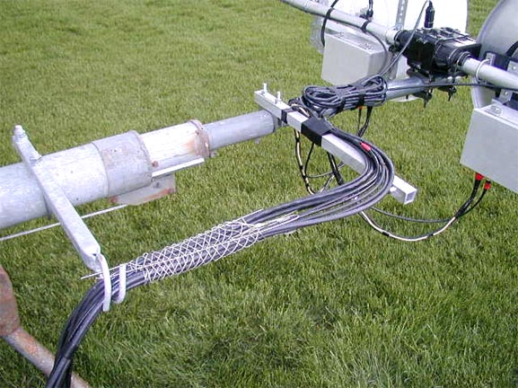
The slug of cables are supported from a homebrew stand off and an extra coax guide left over from my other tower installation. The wire mesh around the cables are electrical contractor type "Kellums Grips" These tighten as the cables pull down, like a Chinese finger puzzle if you know what I mean. It keeps the strain off the 90 degree turn as the cable route to the mast.
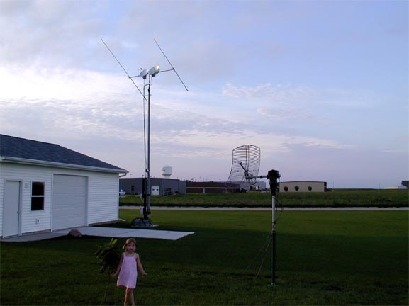
Below is the completed tower project with the dishes and VHF / UHF Yagis. At this time (10-2002) the 5.7 GHz is still running barefoot, 250 mW. I am currently working on getting the 5.7 GHz amplifiers.
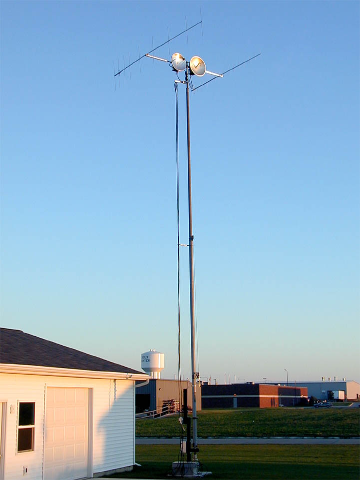
In addition, it turned out that I was able to use the dish tower as the uplink for the A0-40 satellite. The 440 FM yagi works just fine for the U-Band uplink. The S-Band 2.4 GHz downlink is shown on the separate mast in the foreground.
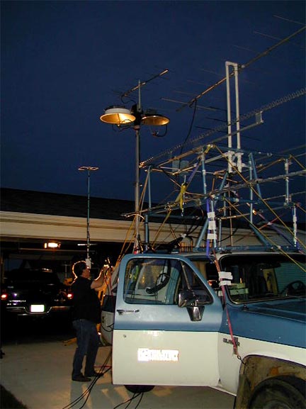
Below is a picture of NØDQS - Gene's mobile setup. 50 MHz thru 10 GHz!
How well does it all work?!
Well, It now works real well. I have managed 17 grids on 5.7 and 18 grids on 10 GHz so far. Best DX is with Bob - K2YAZ up in EN74. 524 Miles / 844 Km was the distance on 8-9-2002. We had a good band opening and Bob was 5x5 to 5x9 on all bands 144 thru 10 GHz! Gene, NØDQS also worked him from the Rover the same day on all bands. In addition, Gene and I worked 8 grids on 5.7 and 10 GHz during the 2002 UHF Contest. We worked 16 grids on both bands during the September 2002 Contest! We would normally peak on 10 GHz and then QSY to 5.7 GHz and its 250 mW was not a problem at that point. Below is a grid chart of the bands to date.
NOTE TO CHECK THE UPDATED GRID CHARTS ON THE MAIN PAGE - THE GRID COUNTS ARE NOW MUCH HIGHER!
|
KM0T HIGH BAND GRID COUNT AS OF SEPT 19, 2003 |
|||||||
|
5.7 GHZ |
25 GRIDS ALL FROM EN13VC |
BEST DX 844 KM - 524 MILES |
|||||
|
EN06 |
EN16 |
EN26 |
EN36 |
EN46 |
EN56 |
EN66 |
EN76 |
|
EN05 |
EN15 |
EN25 |
EN35 |
EN45 |
EN55 |
EN65 |
EN75 |
|
EN04 |
EN14 |
EN24 |
EN34 |
EN44 |
EN54 |
EN64 |
EN74 |
|
EN03 |
EN13 |
EN23 |
EN33 |
EN43 |
EN53 |
EN63 |
EN73 |
|
EN02 |
EN12 |
EN22 |
EN32 |
EN42 |
EN52 |
EN62 |
EN72 |
|
EN01 |
EN11 |
EN21 |
EN31 |
EN41 |
EN51 |
EN61 |
EN71 |
|
EN00 |
EN10 |
EN20 |
EN30 |
EN40 |
EN50 |
EN60 |
EN70 |
|
EM09 |
EM19 |
EM29 |
EM39 |
EM49 |
EM59 |
EM69 |
EM79 |
|
EM08 |
EM18 |
EM28 |
EM38 |
EM48 |
EM58 |
EM68 |
EM78 |
|
EM07 |
EM17 |
EM27 |
EM37 |
EM47 |
EM57 |
EM67 |
EM77 |
|
10 GHZ |
27 GRIDS ALL FROM EN13VC |
BEST DX 844 KM - 524 MILES |
|||||
|
EN06 |
EN16 |
EN26 |
EN36 |
EN46 |
EN56 |
EN66 |
|
|
EN05 |
EN15 |
EN25 |
EN35 |
EN45 |
EN55 |
EN65 |
EN75 |
|
EN04 |
EN14 |
EN24 |
EN34 |
EN44 |
EN54 |
EN64 |
EN74 |
|
EN03 |
EN13 |
EN23 |
EN33 |
EN43 |
EN53 |
EN63 |
EN73 |
|
EN02 |
EN12 |
EN22 |
EN32 |
EN42 |
EN52 |
EN62 |
EN72 |
|
EN01 |
EN11 |
EN21 |
EN31 |
EN41 |
EN51 |
EN61 |
EN71 |
|
EN00 |
EN10 |
EN20 |
EN30 |
EN40 |
EN50 |
EN60 |
EN70 |
|
EM09 |
EM19 |
EM29 |
EM39 |
EM49 |
EM59 |
EM69 |
EM79 |
|
EM08 |
EM18 |
EM28 |
EM38 |
EM48 |
EM58 |
EM68 |
EM78 |
|
EM07 |
EM17 |
EM27 |
EM37 |
EM47 |
EM57 |
EM67 |
EM77 |
Improvements to come will be tightening up the MA-40 rotation. There is quite a bit of "play" or "slop" in the azimuth rotation, so when its a bit breezy, the dishes dance around some. Also, I am working on a video feedback system that will give true AZ and EL figures from the top of the tower. Again, when it gets a bit breezy, the tower sways a bit and being on horizon can sometimes pose a minor issue. I already have a video cable ready to go at the top of the tower with a weatherproof camera. I am currently looking for a digital compass to install at the top. I will use some kind of bubble level at the top for getting feedback on the the elevation control. The camera will be fixed on these instruments in some kind of weatherproof enclosure. I also have ready to go a control cable for DC power for the compass and a light for nighttime operation.
On very hot days, it was noted that drifting was an issue. I always managed, but it was a problem for other folks following me around. So, I need to more securely fasten the transverters to the "L" bracket on the inside for better metal to metal contact. Also, I am going to paint the "Band Boxes" white to reduce the interior box temperature on the hot days. When it was cool, drifting was not much of an issue.
Hope you enjoyed the write-up. Please look for me on the high bands when we get some propagation!
73 - Mike - KMØT EN13vc