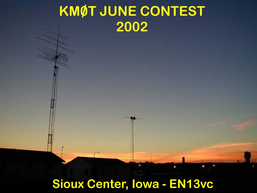
June ARRL VHF Contest 2002
(This webpage has lots of pictures - Please be patient!)
Time seems to fly by when one is having fun as so they say. It also flys by when your watching you kids grow up too I have found, they get so big so fast it is truly amazing. However, time seems to fly by the fastest when one is preparing for a VHF contest. The ARRL June VHF 2002 Contest was no exception here at this QTH. Time was the enemy this year, and I kind of lost! Does this sound familiar to some of you out there? I had fun however making a run for it and learning a lot in the process. That’s really what its all about!
Planning Begins…
For last June (2001), I had worked the previous year on getting good antennas and power on 2304 and 3456 Mhz. I also worked on getting "Rover Boxes" for those bands to borrow to N0DQS. (See June 2001 Results) This all went pretty well and I had very good results over the whole year with these new bands. With that knowledge and experience in hand, I began to think of how to get on 5.7 and 10 Ghz, all in an effort to be up and running by the June Contest 2002.
The Hook!
At the end of June 2001, Donn – WA2VOI came to Sioux Center and brought some portable 10 Ghz equipment. We were going to try to work some contacts to get some states for the CSVHF "States Above 50 Mhz" event. He brought his own equipment and an offset DSS dish setup he borrowed from Gary – W0GHZ. Also, Jim – K0MHC was there to lend a hand and give me some moral support since I had absolutely no experience on 10 GHz.
With Donn’s careful planning and mapping some paths with the "TOPO USA" software, we managed with little effort to work 3 states on 10 Ghz, Iowa, Minnesota and South Dakota.
I sat on my rooftop with the 10 Ghz setup and brought my old Kenwood TR-751 up to the roof for 2 Meter liaison. It was a super hot day and being on the roof did not help matters much in that regard. Donn gave me the maps and told me where to point. When he got to his operating positions, he was always right on the beam heading as he said he would be. It was really neat and I also got to move the dish around a bit, both in azimuth and elevation, just to see how sharp the beamwidths were. Plus or minus a few degrees and bam, he was gone!
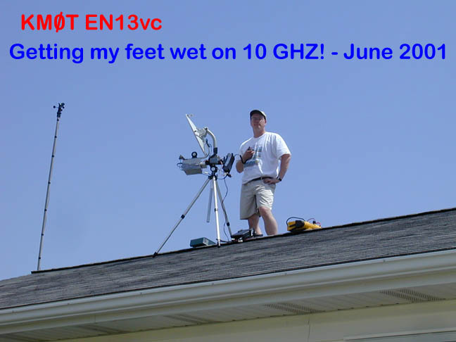
It was a very good experience on 10 Ghz and really got me "Hooked" for thinking about getting on the band. Not to mention that the 3 extra states for CSVHF made the difference between first and second place for the event. Thanks Donn and Gary, I really owe ya!
Tower #2 Project
In late summer of 2001 as I was thinking of getting on the high bands, I still was not sure how I was going to get some dishes for 5.7 and 10 Ghz in the air. I recall Donn indicating that extreme height was not a priority, just enough to get through most of the local clutter to the horizon. This was proved when I was on my roof with the 10 Ghz equipment.
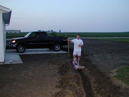
Because of that, I was thinking of putting up 30 feet or so of Rohn 45 next to my garage. I had planned a bit ahead and put a 4" drain tile pipe in the ground from the shack to around the garage, thinking that was where I would put the other tower. Patricia helped me dig the pipe in prior to me landscaping and planting grass in the area. My wife knew I was up to something and kept asking me "what are you doing now?" Well, the cat was out of the bag and I fessed up. She agreed as long as it did not have guy wires. I tended to agree with her on this and knew however it would limit the height.

I had checked on all kinds of tower configs, even fold over types but found that Rohn wasn’t making that anymore. Then out of the blue, Gene – N0DQS found two old Wilson MA-40 crankup masts with rotating bases in Rochester Minnesota. We cruised up there one afternoon with a boat trailer and bargained with the guy. We ended up bringing them home for $325 apiece. Not a bad deal, they were in good shape. A call out to US Tower got me the tower base bolts for a bit over $100 and I began to plan on digging the concrete base hole.
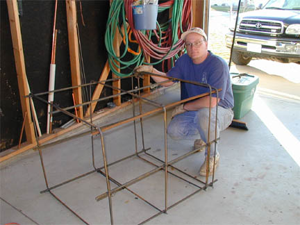
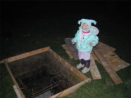
In late October and early November, the base hole was dug and I began working on the rebar cage and grounding. Also made the bolt template and got things all put together to wait for the concrete.

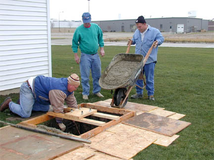
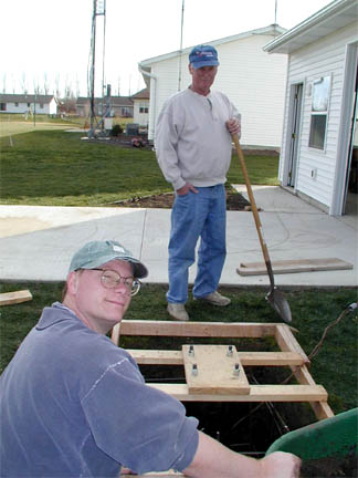
My folks came to visit over the long Thanksgiving weekend and the truck arrived on the Friday after turkey day. It worked out that Dad was there and he was a big help in all aspects. I could not let the concrete truck drive on the new lawn, so it had to be wheelbarrowed in. That cost a few extra bucks cash and the driver and another fellow put that right in their pocket! It worked out very well and some rain started falling as soon as the pour was done, got it covered up just in time!


902 Woes…
The 902 amp during the previous January contest was only putting out 50 watts. It was normally good for over 150, but along the way I had done something to it by overdriving it, etc. I spent considerable time on the net and talking to various hams about the internal components. It all turned out that the components were some type of dual type power gasfets and were labeled under a SRF number. I was told that in lieu of a MRF number – Motorola RF device, it was a "Special" RF device manufactured by Motorola for OEM use. The amp was made by Powerwave and getting information on the SRF number was not to be found anywhere. Below is the inside of the amp, the two SRF devices are the white boxes on the left half of the amp.
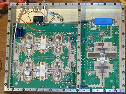
I called Powerwave’s tech support and I ended up discussing this with someone who was also a ham. He indicated that the part was proprietary equipment and still being used in current production models, so no information about what was in the package could be released. He also indicated that they were not set up to sell parts. So I was SOL. (If anyone knows where I can get replacement parts, please let me know.)
While I was wondering about what to do about some decent power on 902, I came across a post from John - N8UM and he was letting some equipment go on the market. He had a SSB LT2S Mark II - 2 Meter transverter for sale.
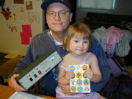
I had been looking for one of these for years and began to discuss with him about it’s particulars. In addition, he indicated in an email that he had one of the Terry Price – K8ISK modified 902 amps that he was not using, in fact he had never put it to power and decided to let that go as well. It was a bigger amp than the one I had, so all the better. It was 28V solid state with low input drive requirements just like the one I had. So just by a stroke of good luck I came across this bad boy and began to get it all set up. John also sent some stickers along for Patricia! Thanks John!
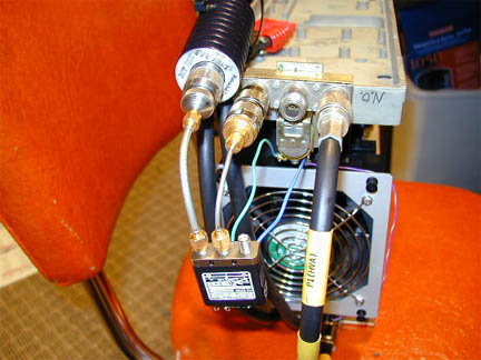
I got the amp set up and hooked into my system to begin testing. It took a bit rework since it had a N-type coax relay in lieu of the SMA relay I had on my other unit. The amp worked wonderfully and put out over 225 watts on 902 Mhz. It appeared the only limitation was my ability to keep it cool and if I could deliver enough current at 28 volts.
As I proceeded with the testing, I noticed I was not hearing the local QRM from cordless phones in the neighborhood. Strange I thought, so I hooked up the rover transverter and was hearing the local stuff just fine. A bit more investigation pointed to the fact that my 902 SSB Electronics LT33LP shack transverter was no longer hearing anything. Ahhhh, now what did I do? This is what led me to learn about front end gasfets and relay isolation!
Relays, Isolation and Gasfets - Oh My!
I tell you there are a lot of folks out there that can sure help a guy out when in time of need. This case was no exception.
A bit of asking around led me to believe that the front end gasfet on the receiver chain of the transverter was toast. In addition, the old N type relay on the new 902 amp was probably the culprit. At the higher power level of the amp, the relay was apparently letting too much energy through and proceeded to kill the front end device.
I took the gasfet out, which was kind of a chore, never having done it
before. But it’s an experience to be had by all. Putting the new one
in was no sweat. I am no longer afraid of it and should be able to do it
the next time it happens!
The schematic had shown that the gasfet was an old MGF1200. Most folks from the
internet said it was a MGF1302. Then a lot said it could be replaced by a
MFG1402 or the newer ATF devices.
It was getting close to contest time and I had lots of advice on what to do. However, Marc – WB0TEM came through for me with flying colors. Marc lived fairly close to the QTH here and I took the transverter there for a fixing. He had a substitute gasfet (ATF10136) and slapped it in there. He then put it on his noise figure meter and got the unit measured. 1.4 db noise figure was right were the spec sheet said it should be so we left the bias adjusting alone. It was a real neat trip to Marc's, he told me many stories of EME from the old days and showed me all the projects he was working on. The antenna farm for EME and tropo was very impressive; most things homebrew there. Very neat to see what one can do when they put their mind to it. His work bench of equipment and experience in building things sure shows. Thanks Marc!!
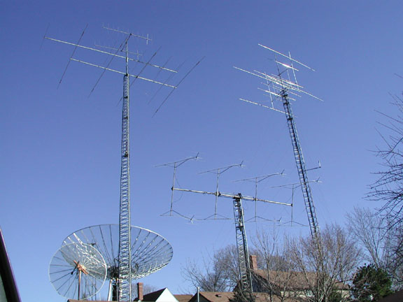
The Antenna farm at Marc's QTH - WB0TEM - Akron, Iowa.
Then off to solve the problem of the leaky relay. A few suggested putting
a few relays together so to provide more isolation for the RX side. Then
put a dummy load on the good isolation relay to put the RX on the dummy during
the TX cycle. This seemed like a good idea.
So the solutions seemed to be that the N type relay had the poor isolation, then
use a SMA relay for the RX dummy load transfer. Or use just a SMA relay
alone; however some said that the power handling capability was low. I
could not find any hard data, but Gary, W0GHZ said that specs he looked up said
200 watts at 900 Mhz. K8ISK, Terry indicated 250 watts is easily handled
by an SMA relay. Many other emails indicated they said 10 watts to 50
watts, etc. All across the board. No hard data was found by me however.
My own experience with SMA relays at 900 Mhz indicated that they handled 175
watts no problem using my old 902 amp. It ran 3 contests full bore with no
relay issues. (However I fried the amp due to overdrive :)
The new amp put out 250+ watts, so I was kinda torn about using just a SMA, so I
used the two relay scenario.
Chris, N0UK indicated that I needed to be aware about cascading the relays, not
directly together. He suggested I look up in the VHF/UHF DX book from the
RSGB. It indicated that one should use a 1/2 or 1/4 wavelength length coax
in-between depending on if your relay terminates the open positions to ground or
not. So I went with that suggestion and made up a 1/4 wavelength coax.
There is a good article on that subject in the manual, it explains it very well
and worth the time of a good read.
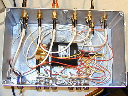
KEEP IN MIND I DID THIS WRONG! If you look at the relay layout as shown and compare it to the VHF DX Book, you will see that the RX should be connected directly to the 50 Ohm dummy load via the SMA Relay while under the TX condition. My configuration is wrong, but it works. I discovered this as I did the diagram for the webpage. SO - YOU HAVE BEEN WARNED. (better to be lucky than good apparently.....)
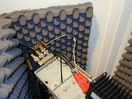
Note the foam, the amp fans make alot of noise, it gets a foam cover also on the top during the contest. The foam works pretty good!
So about a week before the contest, all was tested and appeared to be in good working order. I was again receiving the local QRM on 902 Mhz and the gasfet was holding after some high power testing. (AGAIN - SEE MY DISCLAIMER ABOVE!)
In the mean time….the tower take shape.
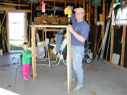
Sometime during the winter, my good friend from high school - Tim Link stopped by for a visit. Tim is a salesman for outdoor adventure type of clothing and gear. He enjoys adventure trips and mountain climbing, etc. He gets into town on occasion and helps me out with a few things now and then.
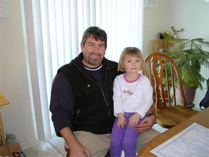
Tim and Patricia
In fact, Tim was in the shack when I worked the VK opening on 6 Meters back in September of 99. So now when he calls, he always asks if the VKs are in! I just have to say no, and that he needs to stop by in about 10 years when it happens again J
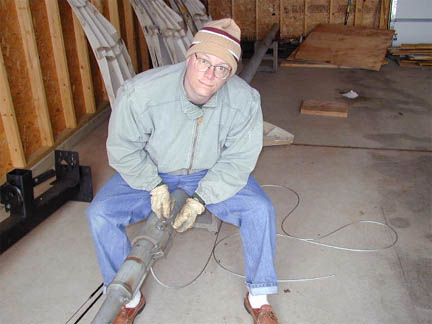
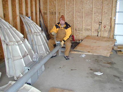
So Tim and I disassembled the old tower in the garage and cleaned it up good. I also had purchased some winches for the raising fixture as well as the crank up winch. We got the crank up winch installed and routed a new 3/16" cable. It all came together real well and was ready to put on the pad.
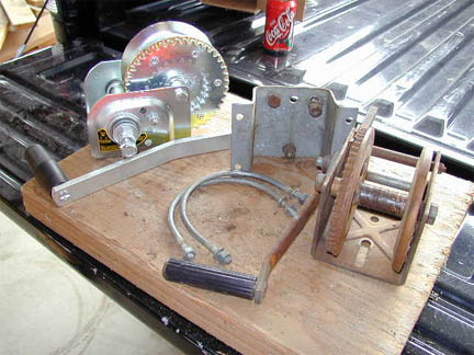
Below is the new cable attachment to the bottom of the inside tube. Also here is the upper collar / pulley assembly.
Then the final reassembly....and Tim testing the winch...
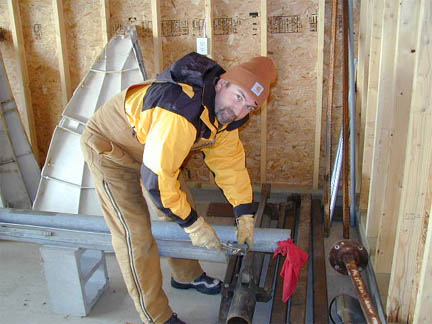
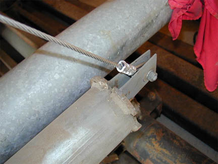
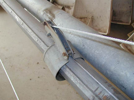
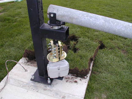
During the spring, Gene – N0DQS stopped in for a visit and we put the raising fixture on the pad and installed the tower in its horizontal position. At that point, we installed the raising fixture winch and cable.
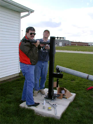
As it turned out, the cable clamp for the tower I built out of some heavy u-bolts and angle iron did not hold up and bent immediately upon raising the tower. So I ended up ordering the raising fixture clamp from US Towers. That worked out very well and I then proceeded with the rotor installation. That worked out pretty well except that since the raising fixture was a custom built unit by a welding shop, the bolt holes for the M-Squared Orion rotor did not line up too well. A little work with the grinder and sawzall solved that and I got the rotor in place.
IF Switch Retrofit for the Shack and Rover Modules:
Since I was thinking of adding 2 bands, 5.7 and 10 Ghz, I needed to retrofit my SMA relay IF switchbox. Currently it was set up for 4 outputs. Also, the control box was a standard 4-position pushbutton for AV switching. This all had been working very well and was used in the shack for switching from a 144 IF to my 902, 1296, 2304 and 3456 Mhz transverters. It also controlled the PTT routing and some relay switching to share a LMR1200 feedline for 902 and 1296. (See my IF Switchbox projects from the 2001 January VHF Sweepstakes Contest for more info and details for building these boxes)
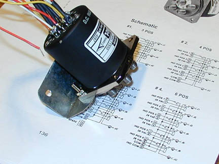
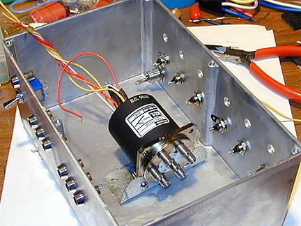
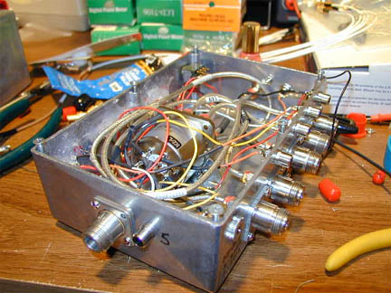
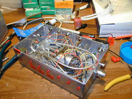
With the relay being a 6 position SMA type, I still had two spare positions to switch. I took the switchbox apart just enough to get two more outputs installed and then stacked two of the 4 port AV switchboxes to get at least 6 positions of control. The forth position on the first box simply selects the second box controls. I would have gone a different route for control, except I could not find a 6 position switch that pops the other 5 out when selecting any one of the 6 positions. This turned out to be no problem however and works very well. It sure is a good way to maximize your IF rig use. Here are some pictures of the updated shack IF switch, it has a 6 position SMA relay, 28V, pretty common and easy to find on eBay.
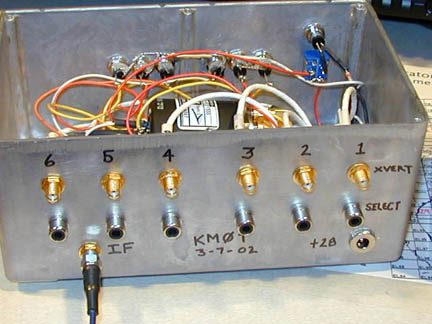
Here are a few pics of the control box and the cabling behind the control box.
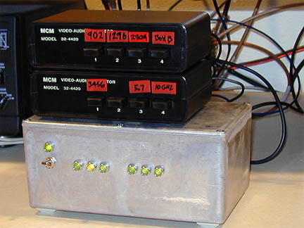

I also updated the rover control box and IF switchbox to 6 positions in order to handle more bands. This work was able to be done during the winter, but just was another task that had to be completed to get ready for June. Below is the rover IF switchbox, it has a 6 position SMA relay, 12V. The 12V version of this relay is very rare and hard to find.
Planning the 5.7 and 10 Ghz Band Additions:
This project was pretty ambitious for me since I had little to no experience with parabolic dishes and other issues related to getting on these bands. It is definitely a story in itself and warrants a separate write up detailing all the trials and tribulations I experienced.
What it all amounted to was that I got the tower project done and the dishes up there just in time for the contest. We also got the same equipment mounted on Gene's rover just before the contest. However, we only managed to make one contact and realized that we had fried the front end gasfets on the 10 ghz transverters. Some other equipment problems also arose and this set us back the first few hours of the contest. With that, the 5.7 and 10 ghz bands were scrapped for the contest to be worked on in the future. See my 5.7 and 10 Ghz project write-up for all the details.
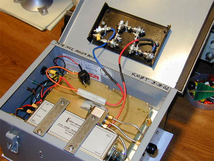
Rebuild of the 3456 Mhz Rover Box - "I need more power Scotty!"
Sometime during the winter, I also built a new 3456 Mhz rover box for Gene, N0DQS. I had come across those amps on eBay that were going for about $150 for 40 watts at 3.4 Ghz. It was a great value and the whole thing turned out wonderfully. The specs were that the amp needed 0 dbm of drive (1 mW) and at 12.4 volts. According to "PyroJoe" of eBay, these units needed 12.4 volts regulated at 15 amps or so in order to not be too wide. The transverter box I already had made was a "15 watter" and worked fine, I just thought since these amps were available, might as well try to integrate one and see what happens!
First off I knew the heat generated by the amp would be alot, so I began fabrication of the heat sink and fan assembly.
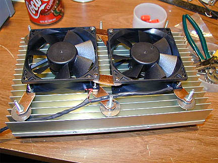
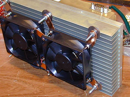
After the fans were mounted, I used a old "Hoffman Box" obtained from my Father-in-law, Bernie. He found the metal box for $5 and it was pretty heavy duty. It was the only thing I had laying around so I worked it into the plan. The heat sink fit in very well with the amp on the top. Screws through the side of the box into the heat sink and some standoffs on the bottom keep the fans away from the very bottom of the box. Note the internal plumbing and wiring prior to the transverter installation.
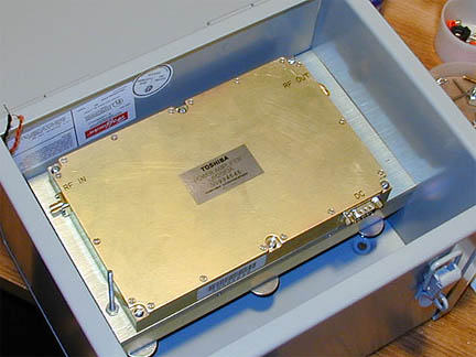
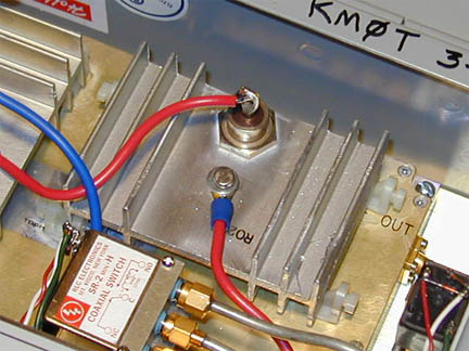
In order to drop the voltage, I strung a bunch of power diode together. Well, this seemed to work but when I measured their V-Drop, it was when they were not in conduction. So when I powered it up and drew some good current, the voltage to the amp was around 11V or less....Hmmm I thought. That's when I knew the cobwebs covering up my basic electronic theory needed to be cleaned out! These babies also got really hot, so I went back to the drawing board and came up with a heat sink mounting and it turned out I only needed two diodes. (Thanks to Matt, KF0Q for the power diodes and Dale, WA9ENA for the heat sink material!)
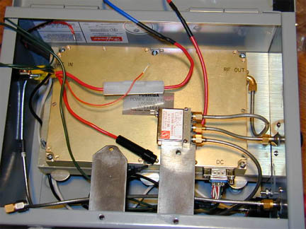
Even with the little heat sinks, the diodes got very hot. So I mounted some small fans on them for the completion of the entire unit. Note the small computer nylon motherboard standoffs I used to insulate the small heat sinks from ground. These are glued on the Toshiba amplifier cover with model airplane grade super glue and have not given any indication of coming off. If they do, KABOOM!!! (they are fused however) The heat sinks are positive with respect to ground due to the diodes being bolted to them.
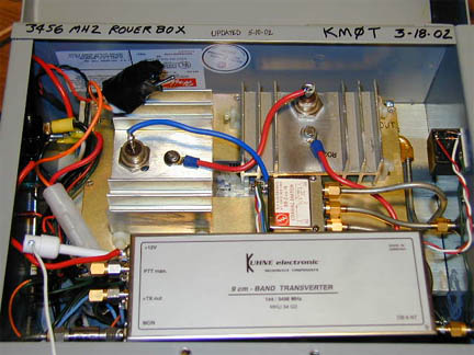
The small relay on the the right side inside the Hoffman enclosure is for PTT control of the amp. One cannot use the PTT that is used to drive the transverter from RX to TX mode for the amp at the same time. The pin that needs to be brought "low" on TX enable is TTL logic and tends to keep your manual PTT "high". That did not work too well and it made the transverter act pretty strange! So the relay is used on PTT control to send the TX enable pin on the amp directly to a separate ground via its isolated contacts. Then it worked like a champ.
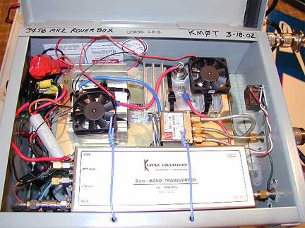
The final product was completed on 5-10-02 as shown with the fans mounted. The total system worked great and gave a solid 40 watts out on 3456 Mhz. Throughout extensive burn-in testing, things only got warm. The fans worked very good. (Update 10-20-02 - this unit has been through a few major contests now and many miles of bumpy roads with N0DQS, it has been extremely solid!)
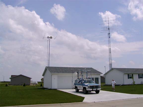
The 2nd Tower Gets Completed:
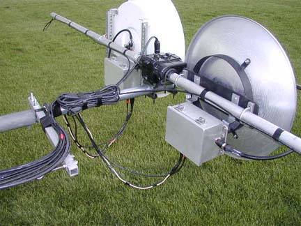
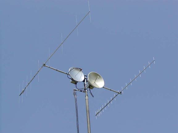
A few weeks before the contest, the final work took place on the 2nd tower. Cables were run and dishes and antennas mounted. It was a fun project and seemed to work out pretty well. Here are a few pictures of the final assembly.
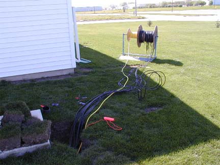
Things were going pretty well right up to the end, but time was running out! Equipment had arrived late and lots of late night building had begun to take its toll. I even took a day off from work to do alot of the cable assemblies. This all seemed like it was going to work out until a big storm rolled thru on the Friday night before the contest.
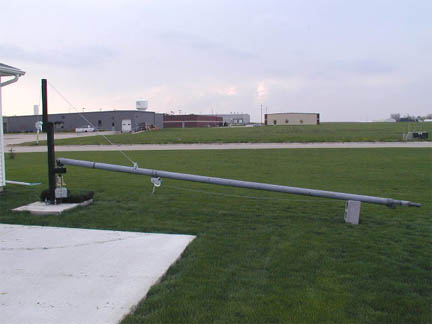
The thunderstorm looked harmless enough and I was working on the new tower as it was laid on its side (MA-40 crankup mast). It started to rain a bit and I thought I would hang out in the garage and watch the storm go past. Well, as the wall cloud hit, the winds immediately jumped to 50 MPH. I quickly ran into the house and swung the other tower's antennas into the wind. As I did that, the winds jumped to 56 MHP. Not a problem, my main crankup tower was nested all the way down. We had seen 56 MPH a number of times here and I was not worried. Well, it got worse and I saw the wind meter jump up to 69 MPH. Below is a picture of the "harmless wall cloud". When I was out in the yard taking this picture, there was no wind to be found. Boy did that change quick!
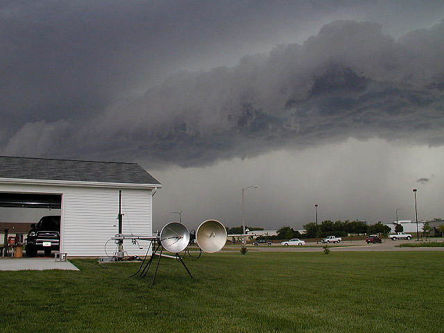
( I had always thought that my wind vane / anemometer had "mechanical limitations" since I had never seen it above 56 MPH. Boy, was I wrong. :) My wife and I got pretty excited and brought Patricia downstairs, as we did that the whole house was shaking and I thought the pictures were going to fall off of the walls. It truly looked like a hurricane outside, just like when you see those reporter guys on TV standing out in the horizontal rain fall, it was very scary. Well the winds gusted up to 75 MPH on my "mechanically limited" anemometer and that's when I decided to go downstairs. Official weather service wind speed was clocked at 77 MPH in the next town. I managed to sneak a look at my main tower during it all, I really thought I was in trouble. Wish I had the video camera going, it was quite a show!
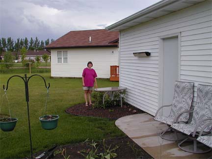
It simmered down a bit and my wife said, where is our patio table? "I told you to bring it in!" I groaned and said, "Oh, there it is, on one of our trees" At least it was not broke! The wind lifted that glass table at least 30 feet off our back patio and set it down right side up!
It must have been an awesome wind, because the antennas and mast turned
inside the rotor clamp of the M2 rotor on the main tower. I lost about 30
degrees of rotation. (still need to recalibrate it) The tower survived and all
the antennas. I do believe their 100 MPH survivability claims now for the M2
line of antennas. All nearby residences and neighbors who had trampolines that
my kid likes to jump on are no longer in the county. My wife and I think that
was the good part of the storm!
Anyway, that set me back all Friday night for tower work! Glad it was not
worse.
Final Preparations:
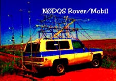
Gene, N0DQS/R showed up on Saturday late morning. We had to mount the
dishes on the rover and test out the new 5.7 and 10 Ghz equipment. We
actually got the dishes on the rover about 10 minutes before the contest
started! The tower was only raised an hour before the contest, talk about
waiting to the last minute!
We then tested and all appeared to be ok. Got one contact on 10 Ghz and 5.7 and the N0DQS/R set off on his journey. Well, as he went out to some grid corners, it appeared that he was not hearing me at all, even when I was hearing him very well on both bands. (That part was exciting!) He came back and we tested things out, He could get no more than a mile or so and then would not hear anything. We then scrapped the 5.7 and 10 Ghz plans for the contest. Oh well, we tried. (It turned out to be another lesson in Gasfets and relay isolation! See my 5.7 and 10 Ghz write-up for more details.) Here are a few pictures of the systems and final integration.
So, as you can see, time was the enemy and we were not able to really get the 5.7 and 10 Ghz up and running correctly. Next time I will try to give myself a bit more time!
The Contest:
Conditions were fair to poor during the contest. We had a few brief 6 meter openings to 4, 5 and 7 land (and a smattering of stations out east), but nothing like last year. Also, activity seemed to be a bit down, but that was probably due to propagation. Made some SSB meteor scatter contacts out east on 6 Meters. I discovered at the last second that my WSJT software was not running correctly, so I lost out on a bunch of late night QSOs. Sorry to those who I had scheds with, I was not able to come through on those.
2M was fair to bad. Made one contact to EN60, that was the farthest east. Got into EM47, 27, 19 and 17 and DM98 to the south. Got into EN16 and EN25, 35 to the north. Never heard Bill - K0AWU - EN37, which was unusual. Got to work the DN95 guys too on 6M and 2M. Never heard DM79 on 2M, normally hear them on Sunday early afternoon it seems. Never found Bob - K2YAZ in EN74, he is usually always workable on 144 and 222 Mhz.
The rest of the microwaves up thru 3.4 Ghz worked wonderfully. The new rover box on 3.4 Ghz with the 40 watt Toshiba amp showed its stuff, never a problem. Always as strong as the 25 watts on 2.4 Ghz from the N0DQS/R.
Not a whole lot of other things to report on during the contest. It was fun, but the propagation could have been better. I understand that the guys out east had good conditions again….arrghh! ( good for them however :)
Contest Summary: KMØT
| Band | QSOs | Pts | QSO Pts | Grids |
| 50 MHZ | 203 | 1 | 203 | 94 |
| 144 MHZ | 74 | 1 | 74 | 38 |
| 222 MHZ | 30 | 2 | 60 | 22 |
| 432 MHZ | 39 | 2 | 78 | 23 |
| 902 MHZ | 17 | 3 | 51 | 15 |
| 1296 MHZ | 19 | 3 | 57 | 15 |
| 2304 MHZ | 15 | 4 | 60 | 13 |
| 3456 MHZ | 13 | 4 | 52 | 13 |
| 5760 MHZ | 1 | 4 | 4 | 1 |
| 10 GHZ | 1 | 4 | 4 | 1 |
| Totals All Bands | 412 | 643 | 235 |
KM0T CLAIMED SCORE: 151,105 SOHP
Not like 2001 (283,725 / 524) but more like the year 2000 score of 136,408 (433 qsos in 2000, but only 50 mhz through 1.2 ghz that year)
"The Rover’s Corner" ©
What can I say, the rovers helped out. Here is the chart of Rover activity I worked:
| BAND | N0DQS/R | KB9C/R | W0GC/R | KB0QGT/R | N0LAN/R | E-SKIP/R |
| 50 MHZ |
12 |
1 |
4 |
|||
| 144 MHZ |
12 |
2 |
3 |
2 |
2 |
|
| 222 MHZ |
12 |
1 |
||||
| 432 MHZ |
12 |
1 |
2 |
|||
| 902 MHZ |
12 |
1 |
||||
| 1296 MHZ |
12 |
1 |
||||
| 2304 MHZ |
12 |
1 |
||||
| 3456 MHZ |
12 |
|||||
| 5760 MHZ |
1 |
|||||
| 10 GHZ |
1 |
|||||
| Total QSOs |
98 |
8 |
5 |
2 |
2 |
4 |
Total Rover QSOs = 119
Rover QSOs % of Total QSOs = 28% WOW! Who says rovers are not necessary? (nobody actually…) This is down in percentage from last June contest. (179 Rover contacts - 34% total of QSO count) A lot of this is due to poor 6 Meter conditions as well as poor propagation to reach other rovers.
Grid Summary Chart:
Here are some grid charts showing the extent worked on the various bands. These where clipped from Vqlog, a program I am currently experimenting with. I was able to export in ADF format for my contest data from VHFDX (which I feel is superior in speed and ease of use for logging these VHF contests) The data transferred very quickly to Vqlog without any problems. The neat thing about Vqlog is that it has the ability to generate graphs, maps and charts based on the QSO data.
73 and See You Next Contest!
Mike - KMØT EN13vc